Introduction
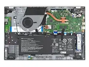
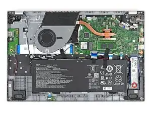
Use this guide to replace the motherboard for your Acer Aspire 3 A315-24P-R7VH Laptop.
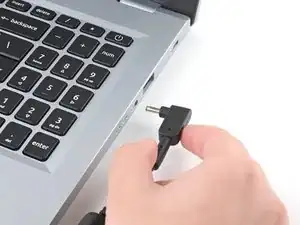
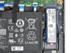
This procedure requires removing the battery to disconnect it. Use care to avoid bending, twisting, or puncturing it—a charged lithium-ion battery can be very dangerous if accidentally punctured. If your battery looks puffy or swollen, take extra precautions.
-
-
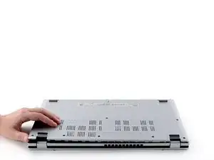
Close the laptop and flip it over on a flat, clean surface.
-
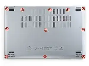
Use a Phillips screwdriver to remove the eleven 6.6 mm‑long screws from the back cover.
-
-
-
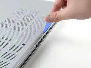
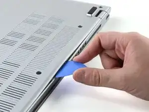
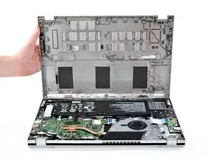
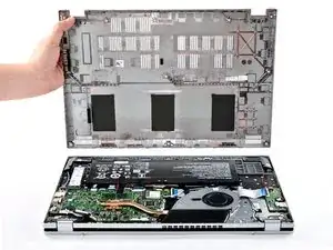
Insert the long edge of an opening pick straight down between the chassis and the back cover at the rear of the laptop
-
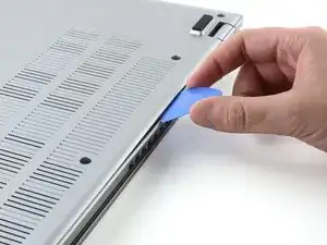
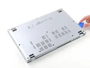
Pry up to release a few back cover clips and position the opening pick flat under the back cover.
-
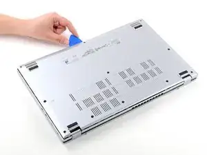
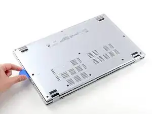
Slide the pick along the rear edge of the laptop to release the clips.
-
-
-
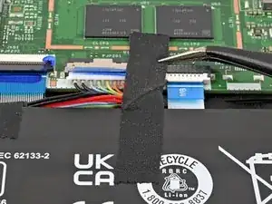
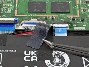
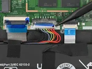
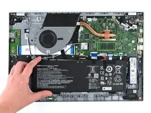
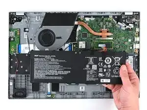
Use the tip of a spudger to push down on either side of the battery cable connector until it comes out of its socket.
-
-
-
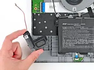
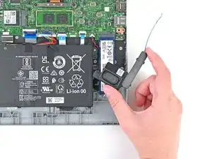
Use the tip of a spudger to push down on either side of the right speaker cable connector until it comes out of its socket.
-
-
-
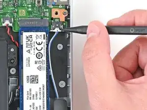
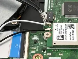
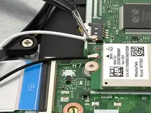
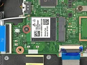
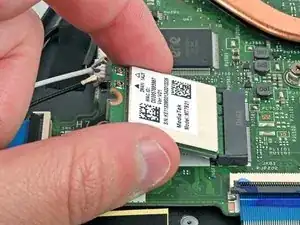
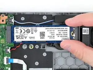
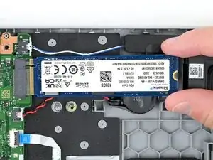
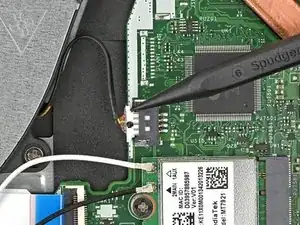
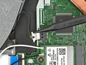
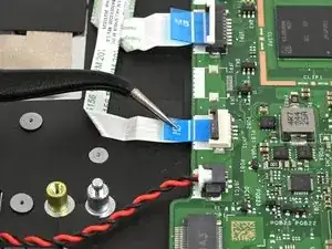
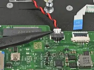
Slide one arm of your angled tweezers under the metal neck of the white cable on the WLAN card.
-
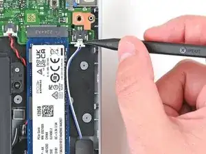
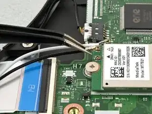
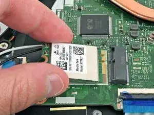
Lift the metal neck to disconnect the cable.
-
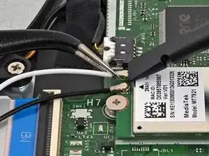
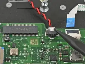
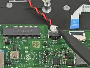
Repeat the same process for the black cable.
-
-
-
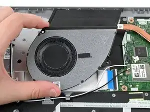
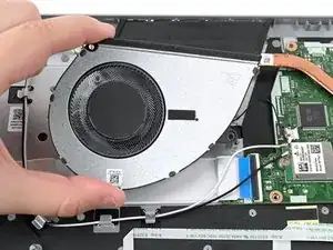
Use the tip of a spudger to push down on either side of the fan cable connector until it comes out of its socket.
-
-
-
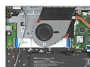
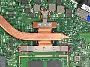
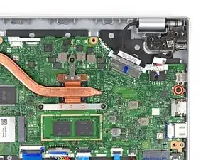
Starting with the screw labeled 1 and going in order, use a Phillips screwdriver to remove the three 4.7 mm‑long screws that secure the heat sink.
-
-
-
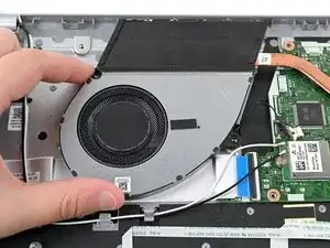
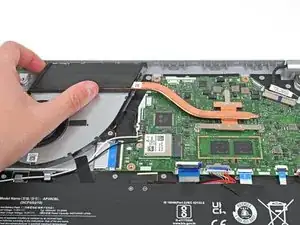
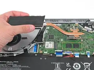
Lift the heat sink to separate the thermal paste bonding it to the motherboard.
-
Remove the heat sink.
-
-
-
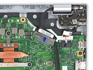
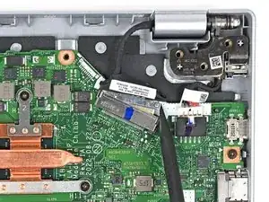
Use the tip of a spudger to push down on either side of the display cable connector until it comes out of its socket.
-
-
-
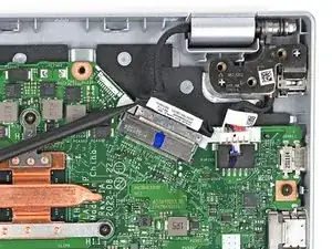
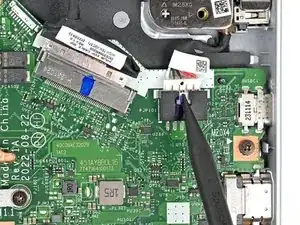
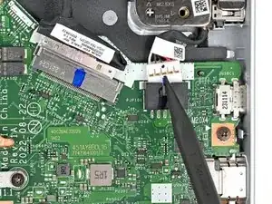
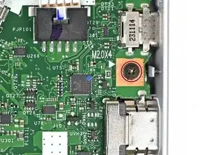
Use the tip of a spudger to push the indent on DC-IN cable connector until it comes out of its socket.
-
-
-
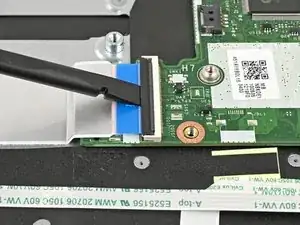
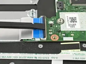
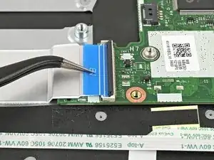
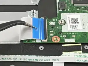
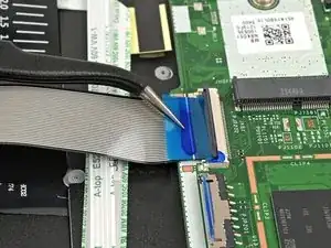
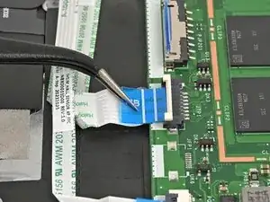
Use the flat end of a spudger or a fingernail to lift the locking tab on the USB board ZIF connector.
-
-
-
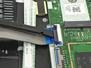
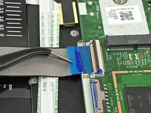
Use a pair of tweezers or your fingers to grasp the blue pull tab and gently pull the cable out of its socket.
-
-
-
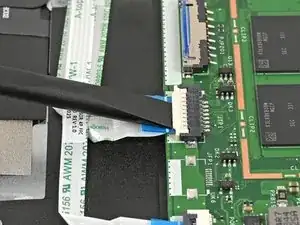
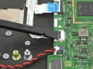
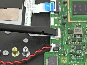
Use the flat end of a spudger or a fingernail to lift the locking tab on the keyboard ZIF connector.
-
-
-
Use a pair of tweezers or your fingers to grasp the blue pull tab and gently pull the cable out of its socket.
-
-
-
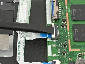
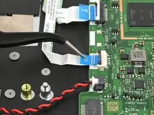
Use the flat end of a spudger or a fingernail to lift the locking tab on the touchpad ZIF connector.
-
-
-
Use a pair of tweezers or your fingers to grasp the blue pull tab and gently pull the cable out of its socket.
-
-
-
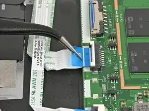
Use the flat end of a spudger or a fingernail to lift the locking tab on the lid sensor ZIF connector.
-
-
-
Use a pair of tweezers or your fingers to grasp the blue pull tab and gently pull the cable out of its socket.
-
-
-
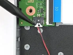
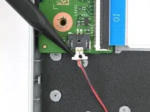
Use the tip of a spudger to push on either side of the RTC battery cable connector and "walk" it out of its socket.
-


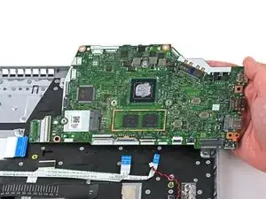
To reassemble your device, follow these instructions in reverse order.
Take your e-waste to an R2 or e-Stewards certified recycler. Acer partners with different e-waste recycling programs that vary by region, click here to see where you can properly dispose of your e-waste.
Repair didn’t go as planned? Try some basic troubleshooting, or ask our Answers community for help.