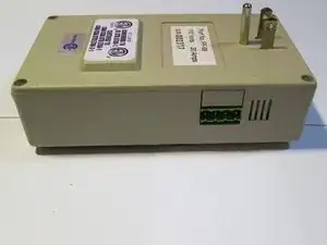
Introduction
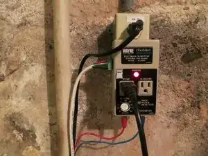
The FF-98 Controller is a mains-powered electronic water level sensor and alarm containing a 120VAC 20A relay for powering a sump pump. It detects water via two single conductor wire probes, one to activate the pump and one mounted higher up to activate a built in alarm if the pump fails. It has an adjustable timer from 0 to 80 seconds that controls how long the pump remains powered after the water level is reduced below the ‘pump’ sense wire.
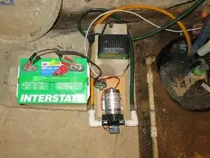
It was desired to have a battery powered backup for the sump pump system. The previous solution was a 12V automotive battery, a charger, and pump, but it would have to be manually disconnected from the charger and switched on if the power ever went out. The secondary alarm sensing function was repurposed to control a second 12V relay which would operate the pump automatically. The battery also powers the detection circuitry of the AC power fails.
Goals:
- Maintain current 120V operation and safety.
- Allow seamless change-over to battery-powered operation.
- Give priority to the 120V pump.
- Provide a 12V PUMP ON indicator.
- Provide a 12V pump test function.
- Disconnect the charger to prevent possible damage while operating the pump.
- Minimal modification to existing circuit board and housing.
If you would like to modify your own unit, a measured drawing is available and you'll read more about that before this post ends. I have also included a full schematic and reverse engineering of the circuit for reference or incorporation into other projects.
-
-
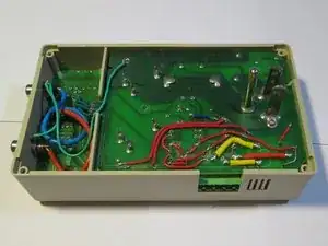
Unscrew the back cover and remove the circuit boards. You will need to unsolder the blue and red wires that go to the RCA phono sockets.
-
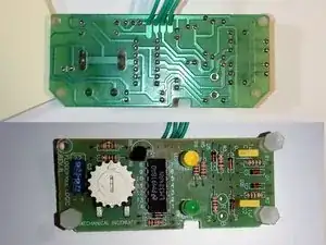
It's helpful to temporally unsolder the smaller logic board and put it aside.
-
-
-
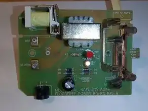
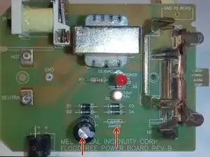
Remove the Jumper, C1 (save it), and the buzzer.
-
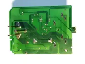
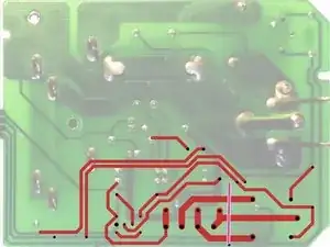
Cut the traces at the white lines.
-
Remove the traces marked in yellow.
-
-
-
Drill holes[black]. Take note of how several holes intercept the existing traces. Be careful to not damage them. Enclosure Cutting Guide can be used as a template.
-
(Ignore the 4 extra holes just under the connector. I forgot to take into account the thickness of the enclosure when originally positioning it. I ended up repurposing some of the incorrectly drilled holes for the extra diodes.)
-
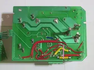
To simplify routing, extend leg 3 [pink] of the SCR and sneak it between the connector and relay. It will connect to the trace going the 120V pump relay.
-
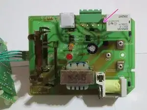
Second picture was taken earlier and does not show the two series flyback diodes for the pump. Also the power supply diode is in a different position.
-
-
-
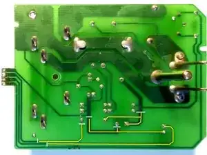
Note the extended lag [pink] of the SCR on the component side of the board.
-
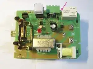
The 2nd and 3rd pictures where taken before I decided to add the pump flyback diodes.
-
-
-
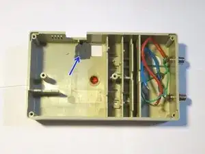
The main housing needs a cutout for the connector. I found it easier to make a slot and then epoxy (and pin) part of the left over piece to the back panel. Otherwise it would be difficult/impossible to angle the PCB back into the housing.
-
(You won't need the plastic patch [blue] inside it you don't accidentally cut the hole for the switch in the wrong place. Again forgetting to base dimensions on the outside edge of the enclosure.)
-
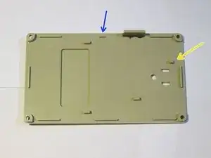
You will need to trim the [yellow] boss on the back as it interferes with the new flyback diode. You might need to trim the [blue] boss depending on exactly where the new wires are.
-
The enclosure datum plane is the parting line for the injection molding. Meaning the flat edge that the back plate contacts when it's put together. The sides have draft and a radius to the front face.
-
If you are marking on the top side, place it on a flat surface and hold something square against the side. This will allow you to reference to the outer-most edge and eliminate the draft angle.
-
-
-
Label is in the project documents section. I printed it on regular paper and covered it with packing tape.
-


For some reason the manufacture only attached the logic board with one screw in the corner so you will need to secure it with hot glue. The relay's datasheet doesn't give a firm answer for the DC current rating for inductive loads like a pump. I added two large diodes (in series) across the pump in the fly-back configuration. Depending on the size of the pump, it may be advisable to add a larger external diode (with limiting resistor) across the pump.
See additional documents for full theory of operation.
Notes:
The battery charger must be capable of automatically float charging the battery so it won't be damaged as it needs to be connected all the time.
The water detection circuit won't work if the controller is unplugged (isn't grounded) even if the battery is powering it.