Introduction

This guide is for the replacement or upgrade of the RAM card.

  1. 5iTmiIH5otPJBJLB
    5iTmiIH5otPJBJLB
    ExqlgbHSmqExlNZC
    IyF4NM53NXR6JFrA
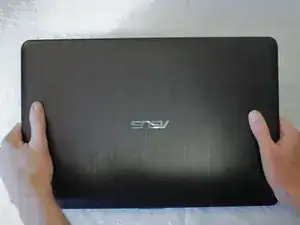
    • Flip the laptop over so that the back panel is facing up.

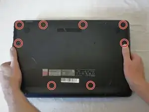
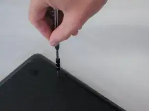
    • Carefully remove the eight 5.7mm screws on the back panel using a Phillips #1 screwdriver.

    There is two other screws that should be removed, each side of the battery. Otherwise you won't be able to remove the keyboard

    jboisseur -

  2. psbBMF6CjnNRLAIZ
    psbBMF6CjnNRLAIZ
    YDBIDNnYulcQwITN
    • Turn the laptop upright and flip the screen open.

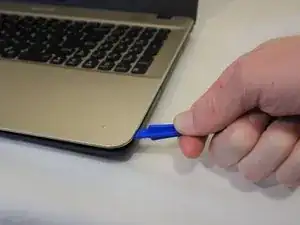
    • Using the plastic opening tool, gently pry the keyboard panel off of the base.

  3. WGL6DwbymoUQGNAO
    WGL6DwbymoUQGNAO
    LBgxJKHFNe6aGjvA
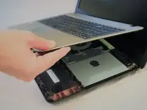
    • Gently raise the keyboard from the base enough to access the underside.

    • Gently pull up on the locking tab to release the ribbon cable. This should take no force to complete.

    • Remove the keyboard.

  4. ix4KdlbOkSpfpRKL
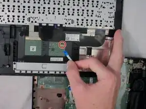
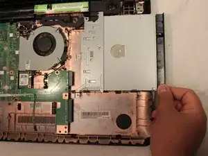
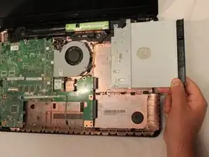
    • Remove the three 5.7 mm screws from the CD drive mounting points. Use a Phillips #1 screwdriver to remove the screws.

    There are only 2 screws, just like the image shows, not three.

    Ted -

    Technically speaking, after these screws are removed the hard drive needs to be removed first. The left screw in the image above pins the left corner of the dvd drive and the right side of the hard drive. The hard drive bracket is on top of the dvd drive bracket, making it really hard to remove the dvd drive first (ie. step 5 and step 6 should be reversed in this guide).

    Ted -

  5. hlteQYuIVmJcaGPD
    hlteQYuIVmJcaGPD
    C4WtHRGOkOIAYTn3
    • Gently slide the CD drive away and pull up to remove it from the computer.

    Removing the dvd drive should happen after the hard drive is removed. The hard drive bracket covers the dvd bracket, making it difficult to remove the dvd drive before removing the hard drive.

    Ted -

  6. VJTqBbIGORcooU4m
    VJTqBbIGORcooU4m
    4d1IRq3NAWXpNMQN
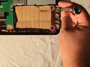
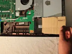
    • Locate the hard drive in the lower right hand corner in the computer. This device did not have a hard drive so a piece of cardboard was used as a substitute.

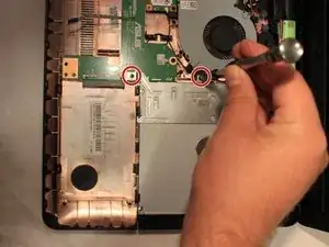
    • Remove the two 5.7 mm screws from the base. Use a Phillips #1 screwdriver to remove the screws. Lift up to remove the hard drive.

    Instructions forget to mention the top right screw in the first image. (The metal shielding is screwed into it.)

    Spun Blue -

    I think you mean the top left, as they have circled the top right screw.

    Ted -

    The previous comment posted here does not make sense, I believe they ment the top left screw. Additionally, if you are following this guide the top left screw will be removed in the previous step when you remove the dvd drive.

    On top of that, the two screws on the right that they do show to remove, and the bottom left screw (that they rightfully don't mention) were actually removed from the bottom of the computer before you take the keyboard off.

    Ted -

  7. CTQRMo4CZuLJ4Huv
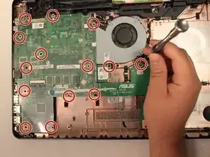
    • Remove all fourteen 4.3 mm screws from the motherboard. Use a Phillips #1 screwdriver to remove the screws.

    There are only 10 screws to remove. On the left side of this image there are 4 spots circled that do not contain screws here. The bottom screw and the one up above it (close to the usb and hdmi ports) were removed from the bottom of the computer before you take the keyboard off.

    The screw above that is present (close to the rj45 port), and needs to be removed. But, there are 2 holes circled above that in this picture which are not screw holes. They look different the other with a ring of solder encircling each hole. These do not contain screws, nor is there anything under the motherboard to screw a screw into. It seems like they might be for additional heat sinks for chips that are not present on this board, which is visible in the pictures below when the board is flipped over to access the ram slot.

    Ted -

  8. k3dCXscsICfqPsTQ
    k3dCXscsICfqPsTQ
    mbk1O46HKKG4wJGL
    XN16D1vOUmNeUvmH
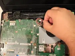
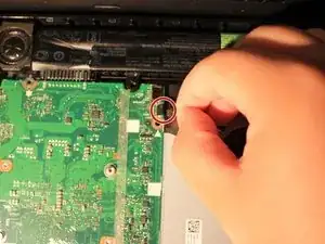
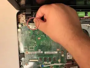
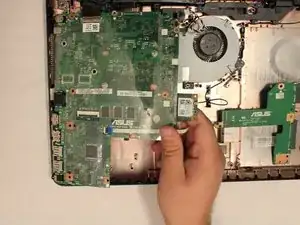
    • Unplug the three connections from the top of the motherboard.

    • Lift up at an angle to remove the motherboard from the computer. Take caution when lifting the areas where the USB ports are located. They are in small slots that exit the computer's main body. They will need to be slid through these slots to remove the motherboard.

    If you are following this guide to work on the Asus R541UA-RS51, there is a fourth connector you NEED to unplug in order to proceed safely. It is in the bottom right of the main motherboard when looking at these pictures, connecting to the small T shaped breakout board that connects to the dvd and hard drive. There is a ribbon cable that needs to be released from its connector.

    Ted -

  9. 3umNZG5LeBBy2s3r
    3umNZG5LeBBy2s3r
    hapmsxMPBwS63Whw
    oNidOerTIBKAKJWK
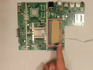
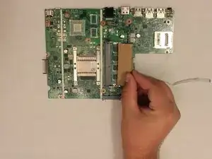
    • Locate the RAM slot on the underside of the motherboard. This device did not have a RAM card so a piece of cardboard was used as a substitute.

    • Replace the current card with the new RAM card.

Conclusion

To reassemble your device, follow these instructions in reverse order.

Drew Singleton

Member since: 31/08/18

365 Reputation

0 comments