Introduction
This guide will attempt to show the user how to safely remove and replace the keyboard without damaging any of the surrounding components.
-
-
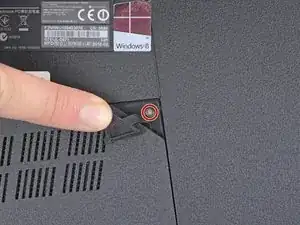
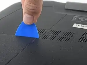
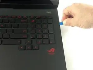
Use an opening tool to pry up the small rubber cover on the upper right corner of the RAM access door.
-
-
-
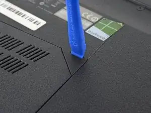
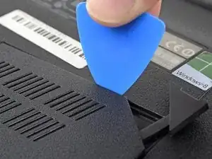
Insert the point of an opening pick in the seam near the top right corner of the RAM access door and gently pry the door up slightly.
-
The door is held in place by small clips around its edges. Pry until you feel the nearest clips release.
-
-
-
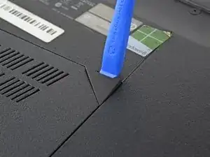
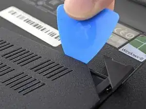
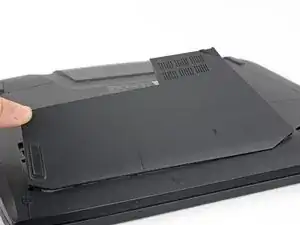
Insert the wide edge of an opening pick into a new part of the seam between the door and the computer.
-
Pry the door up to release the clips closest to the pick.
-
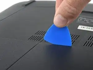
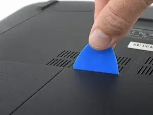
Continue to slide the pick along the seam all the way around the door, prying as you go, until all the clips holding the door down have been released.
-
-
-
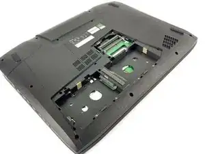
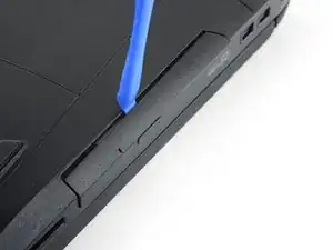
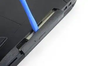
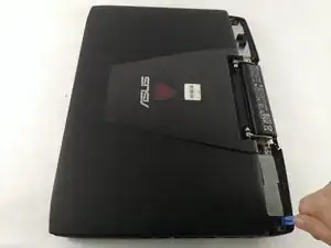
Insert an opening tool into the gap between the optical drive and the laptop.
-
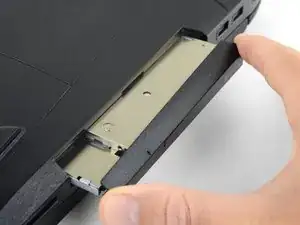
Pry the optical drive straight out of the laptop.
-
Remove the optical drive.
-
-
-
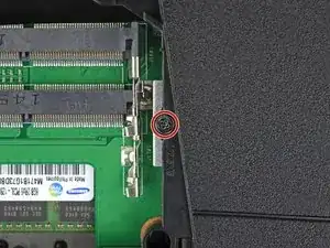
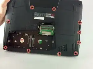
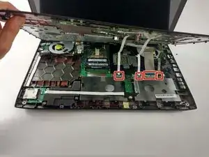
Remove the ten 5.2 mm screws holding the main panel in place, highlighted in the photo, with a Phillips screwdriver.
-
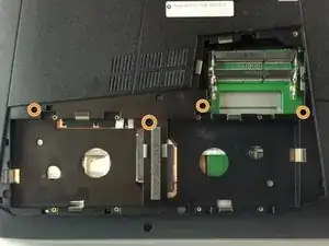
Remove the four 5.2 mm screws underneath the center panel, highlighted in the photo, with a Phillips screwdriver.
-
-
-
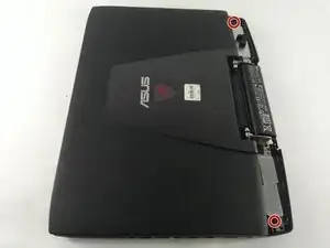
Remove the two 6.8 mm screws underneath to back panel, highlighted in the photo, with a Phillips screwdriver.
-
-
-
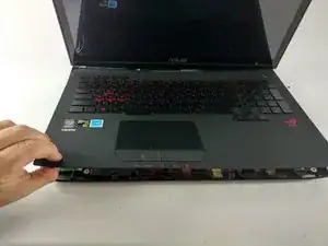
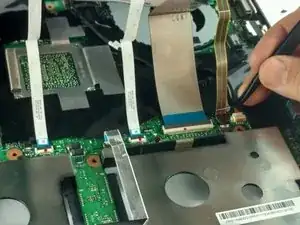
Unlatch and disconnect each of the four ZIF connectors.
-
The keyboard is now fully disconnected and you are now free to lift the keyboard away from the computer.
-
To reassemble your device, follow these instructions in reverse order.
One comment
Great work, but you are missing the last few steps of the replacement as all you are showing is how to remove the upper assembly