Introduction
The Audio-Technica AT-LP120-USB turntable was often manufactured with a faulty preamp, which modifying the noise level and quality electronically. This faulty preamp results in a dampened noise quality, and the only solution is to remove it and replace it with either a newer preamp made by Audio-Technica or another compatible 3rd party device maker.
Removing the preamp involves removing its connections to the device and motherboard, and involves the use of a Phillips #2 Screwdriver, Soldering Iron to disconnect and reconnect the necessary wires and pair of Pliers to clip the wires that cannot be soldered off.
Review the How to Solder and Desolder Connections guide before beginning.
-
-
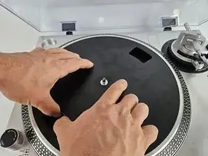
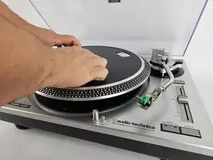
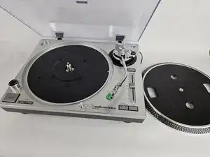
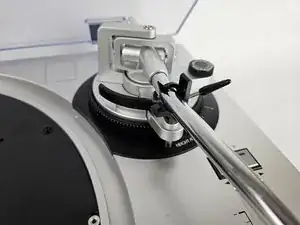
Remove the inner steel plate that spins on the turntable.
-
Carefully lift up the plate.
-
Place it near your device out of the way.
-
-
-
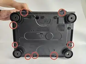
Use a Phillips #2 screwdriver to remove the eight 2 mm screws holding the back casing into place.
-
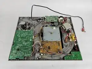
Carefully remove the back casing from the device to expose the interior.
-
-
-
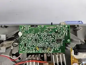
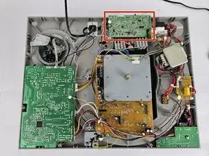
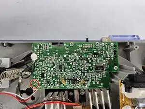
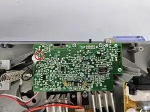
Identify the preamp.
-
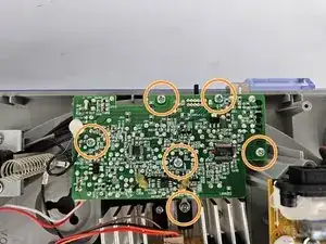
Use a Phillips #2 screwdriver to remove the six 5 mm screws that secure the preamp.
-
-
-
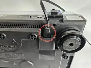
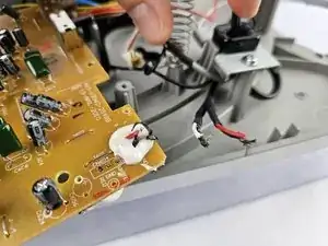
Use the pliers to clip off the black wire connected to the RTV Adhesive Sealant, and burn off/remove the sealant.
-
-
-
Heat up the soldering iron, and wait until it is at its desired heat level. It will be used in the next three steps, so ensure it doesn't overheat.
-
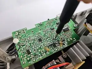
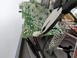
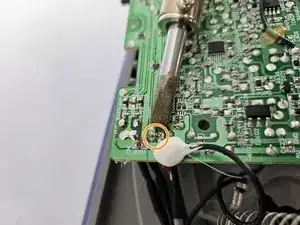
To solder off the white box with the red and white wire in the corner of the preamp, heat up the two metal studs on the opposite side of the preamp as shown, and gently pull the white box until it disconnects.
-
-
-
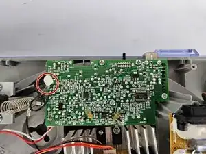
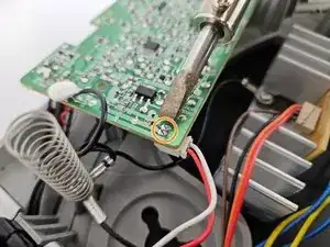
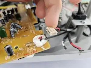
Locate the next soldering location.
-
Use the soldering iron to heat up the two metal joints as shown in the photo, and gently pull the white box containing the wires until it disconnects.
-
-
-
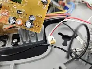
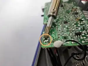
The final location that will be soldered are 4 individual wires, and be sure to take note of their exact order to ensure a proper re-connection later.
-
To solder off the individual wires, hold the heated soldering iron to the metal stud connection points and gently pull each wire until they disconnect.
-
-
-
Once the wires have been cut, soldered and the screws removed, the board will be able to be removed.
-


To reassemble your device, follow these instructions in reverse order, and ensure to solder the wires back on in the correct order according to the preamp model you purchased.