Introduction
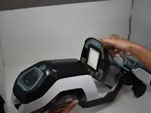
The motherboard and display in the Bissell CrossWave Cordless Max (model 2554A) control the self-cleaning button, various vacuum modes, and different notifications. Without the display, the vacuum would be inoperable and wouldn’t be able to function. Replacement is necessary after the following troubleshooting guide has been tested. The pathway to the motherboard follows the same steps as the battery. The battery wires can remain connected during this removal. It then progresses to the same area of the vacuum where the motor is located. The last steps involve connections from the wires that can be removed before unscrewing the motherboard that is connected to the display on the opposite side.
Tools
-
-
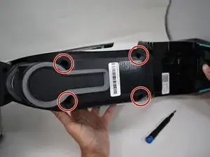
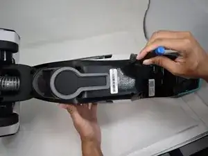
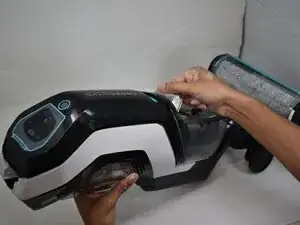
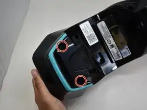
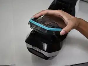
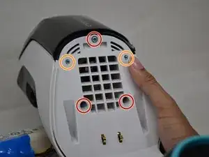
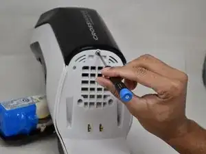
Remove the four 16 mm Phillips #2 screws at the back of the vacuum and below the clean water tank.
-
-
-
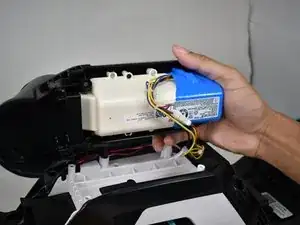
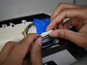
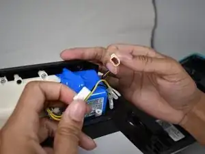
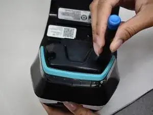
Detach the wires holding the battery assembly to the main body by pressing down on the clip holding the connector together.
-
-
-
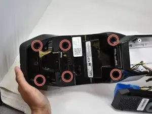
Remove the six 14 mm Phillips #1 screws that are located where the clean water tank once was.
-
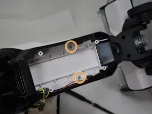
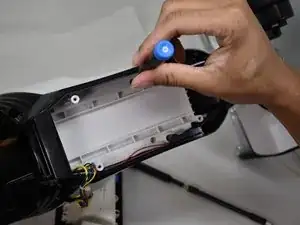
Remove the two 14 mm silver screws located underneath the battery using a Phillips #1 screwdriver.
-
-
-
Flip the device over and remove the three 12.3 mm Phillips #1 screws.
-
Remove two 15 mm Phillips #1 screws.
-
-
-
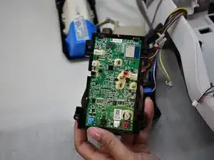
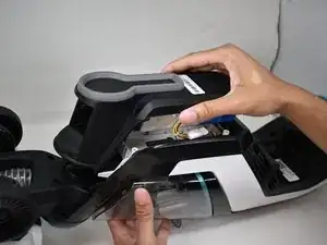
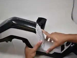
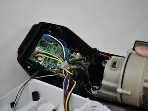
The panel can be flipped over to reveal the motherboard and display.
-
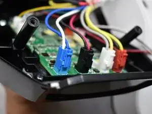
Unplug the nine wire connectors attached to the motherboard of the vacuum.
-
-
-
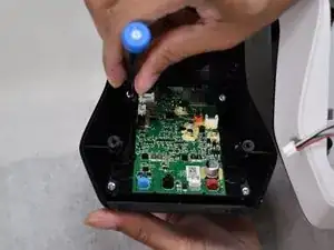
Remove the four 12.3 mm Phillips #1 screws attaching the motherboard to the front plastic.
-
The motherboard can be separated from the front plastic and exchanged for a new one.
-


To reassemble your device, follow these instructions in reverse order.