Introduction

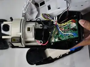
The motor in the Bissell CrossWave Cordless Max (model 2554A) is connected to the display through wires. If the motor is not working correctly, the vacuum is inoperable. This can stem from various issues with the battery and the motherboard. This guide has troubleshooting information.

Without the wires being soldered to the motor, the vacuum will not have a motor. The last step features soldering the connecting for the motor. For good practice, this guide has information on soldering.

  1. KqDrETK3XZuPGGgv
    KqDrETK3XZuPGGgv
    kETUvukBuMHDVGTe
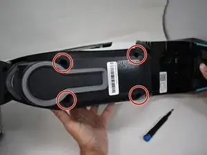
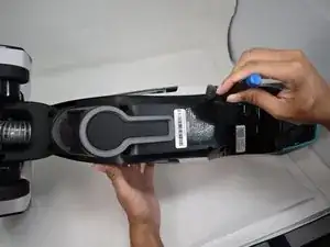
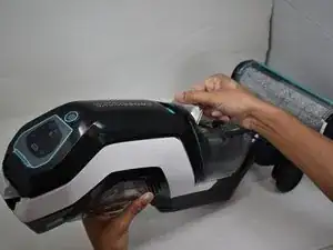
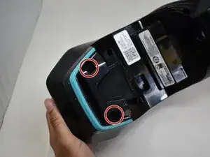
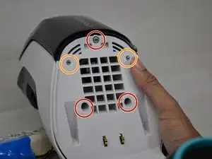
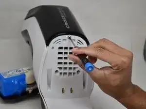
    • Remove the four 16 mm Phillips #2 screws at the back of the vacuum and below the clean water tank.

  2. phxXatw3WcQSBQM5
    phxXatw3WcQSBQM5
    4QAPTVmOrt3SI5Ui
    • Pull the battery assembly away from the main body.

    • There are still wires connecting the battery assembly to the main body. Do not use force to completely separate the two objects.

  3. qAOo6NmCKZjMWZIR
    qAOo6NmCKZjMWZIR
    62PJ3vc1hBSJfFwj
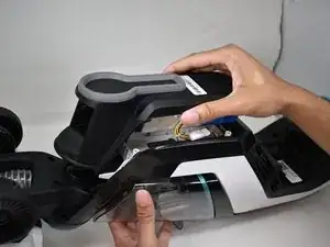
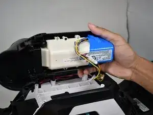
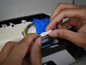
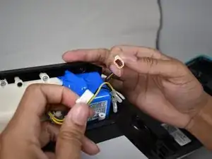
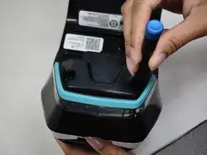
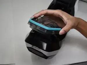
    • Detach the wires holding the battery assembly to the main body by pressing down on the clip holding the connector together.

  4. ohVnOJuB35Bx2JP3
    ohVnOJuB35Bx2JP3
    rDMuD1du145aMVrv
    MFjNRrXx6ngEbRMR
    • Remove the clean and dirty water tanks.

    • Removing the tanks gives access to all of the screw holes required to disassemble the vacuum housing.

  5. 3bUZayDywKrDofKw
    3bUZayDywKrDofKw
    phlZHsgQe1jVKfSS
    BXMvNYgdbGJFnrYt
    • Remove the two 13.8 mm Phillips #1 screws holding the carrying handle to the main body.

  6. dpOmBuB2GDwWO6vA
    dpOmBuB2GDwWO6vA
    JCysTIiVZb5roAMj
    xHfp5WShUYkwI1CQ
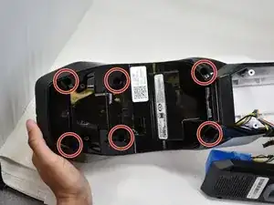
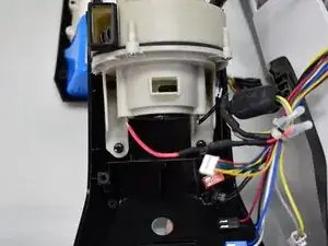
    • Remove the six 14 mm Phillips #1 screws that are located where the clean water tank once was.

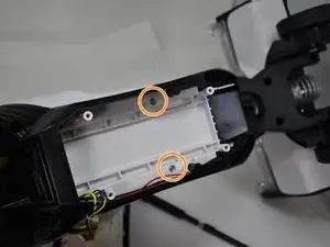
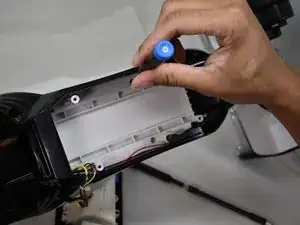
    • Remove the two 14 mm silver screws located underneath the battery using a Phillips #1 screwdriver.

  7. WCwpPfSpPTMXCm4n
    WCwpPfSpPTMXCm4n
    ewKVtGJrHoWXPUPy
    • Flip the device over and remove the three 12.3 mm Phillips #1 screws.

    • Remove two 15 mm Phillips #1 screws.

  8. nJAWLQI2PvMa3ZsX
    nJAWLQI2PvMa3ZsX
    LrLuMWHvdbRIUSa4
    • Remove the two front pieces of plastic from the main body of the vacuum.

    • There are many wires still connected from the main body to these front panels. Use caution when separating the plastic as to not break the wiring.

  9. fvPCiFIFbHVFjF5L
    fvPCiFIFbHVFjF5L
    GDOYAeFWnfPAxfDg
    • The panel can be flipped over to reveal the motor when separated from the main body.

  10. eueX5YOcGBJYOGHJ
    eueX5YOcGBJYOGHJ
    fsfx2JMwLtMGGDNQ
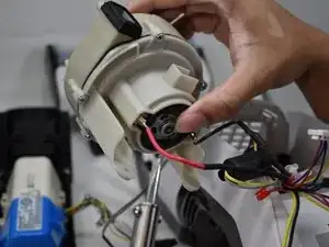
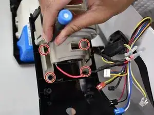
    • Remove the four 14 mm Phillips #1 screws that hold the motor to the front panel of the vacuum.

  11. IqDSZAeRFaeCtC6l
    IqDSZAeRFaeCtC6l
    pMIpKgkZVNtSqnru
    3BNDtdUD2gwkRoFc
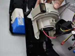
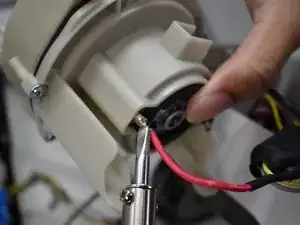
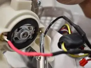
    • The two wire connections can be desoldered to completely free the motor from the rest of the vacuum.

    • Be extremely careful while soldering or desoldering these connections, as the soldering iron can get very hot.

Conclusion

To reassemble your device, follow these instructions in reverse order.

Erin Rodgers

Member since: 01/10/21

346 Reputation

One comment

What dose orange light mean an machine cuts off

Patsy p -