Introduction
This covers disassembly of this drill, fabrication of new motor brushes, and reassembly. While it is specific for this drill, the process is probably generally applicable to many other power tools. I did this and my useless drill now works fine.
Tools
-
-
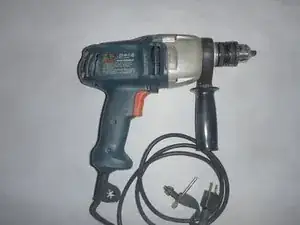
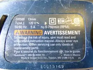
The drill and nameplate are shown here.
-
Replacement brushes are no longer available. This tells how to replace the brushes by obtaining and installing brushes from other sources. This is specifically for the DR500 drill, but the concept may apply equally well to other drills and motors.
-
-
-
Loosen the side handle and work it back and forth while pulling it toward the chuck until it comes off.
-
-
-
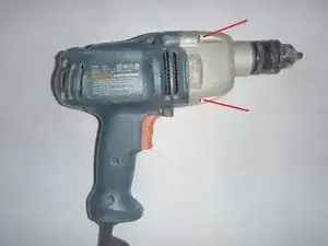
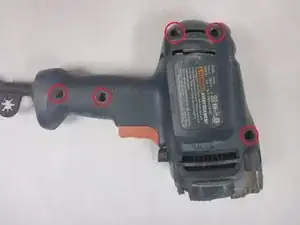
Remove the screws from the metal nose part of the drill body. There are four screws securing it to the plastic part of the body. These require a straight screwdriver or a T20 star driver.
-
Be gentle, they are secured in plastic, not metal.
-
There is no spring force on this part, so it will not fly apart.
-
The location of two of the screws is shown in the picture below. There are two more in the same place on the other side.
-
-
-
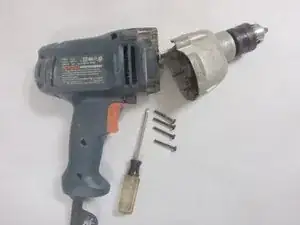
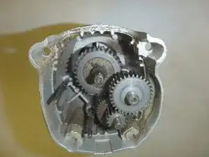
Remove the metal nose part by pulling it forward.
-
Do not tilt this part so that the chuck end points upward or the gears inside may fall out. If this happens, the picture may help you reassemble them properly.
-
-
-
Remove the five screws that secure the two halves of the plastic part of the body.
-
The screws require a screwdriver with a straight tip or a T15 star tip.
-
Locations of the screws are shown in the picture.
-
-
-
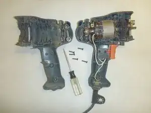
Pry the two parts of the plastic body apart at the seam.
-
Try to remove the half with the label by itself, leaving all the innards with the other half.
-
-
-
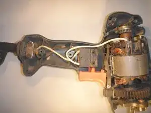
The gearbox is on the chuck end of the drill. It will be removed in later steps and must be reassembled in the same position. Refer to the picture.
-
Observe the location of the trigger and the reverse switch in the handle as well as the routing of the wires.
-
-
-
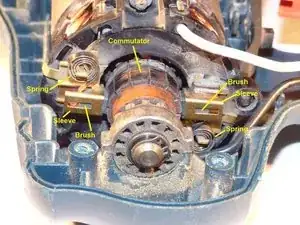
The two brushes are graphite blocks in close-fitting brass sleeves on opposites sides of the commutator end of the stator (i.e. the end of the rotating part of the motor farthest from the chuck end of the drill). The brushes are held against the rotating commutator by brass coil springs.
-
Eventually the brushes wear down and become too short to contact the commutator. This causes the motor to stop running.
-
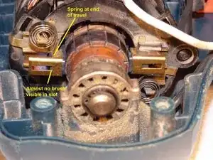
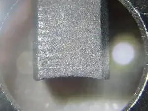
To check the brushes without further disassembly, look closely at the square brass sleeves. Each sleeve has a slot in the side. Looking through the slot one can see the length of the brush. The spring end of the brush should be visible in the slot as in the first picture.
-
If the spring end of the brush is not visible (as in the second picture), it is too worn and should be replaced.
-
Poke a wire or pick between the brush and commutator surface to try to move the brush back and forth in the sleeve. If it moves freely and is not too short, you probably have a completely different problem and you do not need this procedure.
-
If either of the brushes is too short, continue on with this procedure. If either does not move freely, you can continue with this procedure without replacing the brushes (i.e. just clean them).
-
-
-
Before removing anything, estimate the brush length required. Brushes should be long enough to extend at least half way up the slot.
-
Brushes that are too long can be shortened easily by filing them. The shorter the brush, the sooner it will wear out and have to be replaced.
-
In this case a reasonable length is 3/8" (24/64").
-
-
-
Carefully lift the motor assembly out of the plastic case,
-
Pull the rotor from the chuck end to slide it past the brushes.
-
The brushes will catch on the bearing at the end of the shaft. With a pick or wire, pull each of them back into its brass sleeve to allow it to clear the bearing. Be careful when they go past the bearing that they do not spring free and get lost.
-
-
-
When you have the brushes loose, measure the two width dimensions.
-
For this drill, the brush profile is a 0.233" square, essentially 15/64".
-
-
-
The part is listed in numerous internet sites, but all say it is no longer available.
-
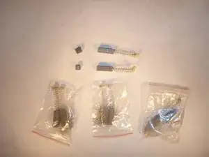
I could not find any suitable 15/64" x 3/8" brushes, but I did find many 15/64" brushes of longer lengths with integral connector springs.
-
On Ebay I got five pairs of brushes described as "15/64" x 15/64 x 11/16" Spring Carbon Brush 6x6x17mm." The total cost for all ten, including shipping from China, was $3.51.
-
These took several weeks to arrive, so if you need your drill soon, you may have to pay more for a domestic source.
-
Some of the brushes are shown. The two small pieces are the brushes removed from the drill.
-
-
-
Mark and carefully saw two of the new brushes to 3/8" length from the end that does not have the spring attached.
-
The brushes are graphite, so they saw very easily. They also crush very easily, so be careful to hold and saw them gently.
-
The cutoff parts with the spring can be discarded.
-
-
-
If the new brushes have a curved end check whether the curve is suitable for use with the commutator. The curve is supposed to be installed so as to match the outside of the commutator. The curvature is very subtle (see picture).
-
In my case, the curve was an exact match for the commutator exterior, so I did not have to do anything.
-
If the curve on the brush is larger than that on the commutator so that the contact point is in the middle of the brushes, that should be OK. The contact between the two will wear an appropriate curve into the end of the brushes.
-
If the curve on the brushes is smaller than on the commutator and there are two contact points (the edges of each brush), the sharp edge may catch in the grooves of the commutator. File down the face of the brush so that it is nearly flat and the contact point is in the middle. An appropriate curve should be worn into the brush over time.
-
-
-
Insert the brushes into the brass sleeves. Be careful to insert them so that the curve in the end of the brushes is correctly placed. The sharp edges of the brush curve should be on top and bottom, not front and back.
-
Once the brushes are in the sleeves, push them deeply into the sleeves and slide the bearing end of the rotor through and past them.
-
Continue to gently push the rotor into the motor housing while using a wire or pick to pull back the brushes in turn until the brushes are on the commutator (this can be deceiving, make sure it is in far enough or the next step will fail).
-
This is a tricky step as the new, longer brushes have a lot of spring force on them and you must hold both back while also manipulating the rotor. A good assistant can be helpful.
-
If the brush was cut too long, file down the cut end until it fits.
-
I do not have enough hands to get a picture of this operation, so you are on your own.
-
-
-
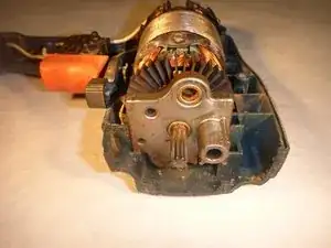
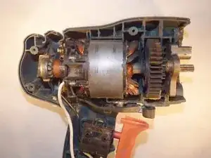
With the innards assembled (motor, gearbox, etc), align the gearbox as observed earlier, match up the gearbox, fan, motor housing, and end bearing with their slots in the case.
-
All but the fan must be correctly rotated to match the housing in addition to being at the proper lengthwise position.
-
The gearbox alignment and the installed motor are shown.
-
When done, turn the splined shaft on the end of the gearbox and observe that the rest of the motor turns easily and smoothly. If it does not, break down the motor and reassemble it.
-
-
-
The reversing lever is the gray piece between the trigger and the upper part of the case.
-
The ball on its inner end fits into the socket at the bottom of the reversing plate on which the brushes are mounted.
-
Its center fits into a recess just above the inner part of the trigger.
-
-
-
Position the wires around the trigger in the appropriate gaps and put the other half of the case on the half with the motor. It should fit easily.
-
If it does not fit, check that 1) all wires are properly positioned, 2) the reversing lever is fitting in its recess correctly, and 3) the trigger lock on the other side of the handle it in its slot properly.
-
Once it comes together, secure it with the five screws removed earlier.
-
Check that the trigger and reversing lever move freely.
-
-
-
Gently press the metal nose with the chuck onto the case. You may need to rotate the chuck or splined shaft to get them to mesh correctly.
-
Once in place, secure it with the four screws removed at the start of this process.
-
Reattach the side handle by sliding it over the chuck.
-
-
-
Run the drill for a few minutes to be sure it works OK and to allow the new brushes to get acquainted.
-
The brush replacement is complete. Use the drill as you wish.
-


Reassembly instructions are included at the end.
7 comments
how many parts in the whole drill
soooooooooooooooooooooooooooooooooooooooooo how many parts?
why would you need to know how many parts are in the drill?