Introduction
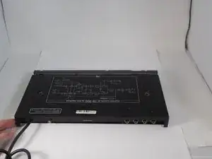
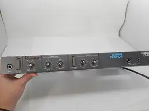
This guide walks you through the process of removing the faceplate from the Boss CE-300 Super Chorus (model CE-300). The CE-300 is a vintage effects processor known for its warm, analog chorus sound. If the faceplate is cracked, obstructs control knobs, or affects usability, this guide will help you detach it safely for repair or replacement.
The faceplate serves as both a protective cover and a housing for control dials, switches, and jacks. Issues such as damaged knobs, loose switches, or visible wear might make replacement necessary. Before starting, set up a clean workspace and gather the required tools, including a Phillips #2 screwdriver, 11mm wrench, and 14mm wrench.
Handle the device with care, especially around clips and cables connecting the faceplate to the internal components. Avoid using metal tools on sensitive parts to prevent damage. This guide is beginner-friendly, so no advanced skills are needed—just follow the steps closely.
-
-
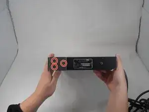
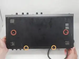
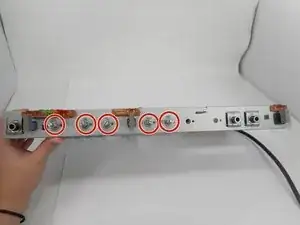
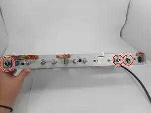
Use a Phillips #2 screwdriver to remove the 3 14.8 mm screws located on the left side of the CE-300.
-
Repeat the previous bullet on the right side.
-
-
-
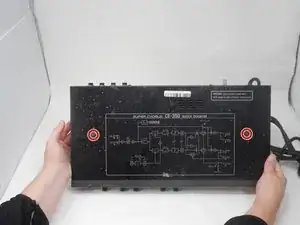
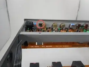
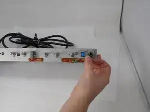
On the left side, remove the one 10 mm screws with a Phillips #2 screwdriver.
-
Repeat the previous bullet on the right side.
-
-
-
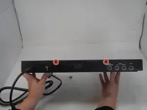
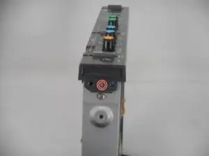
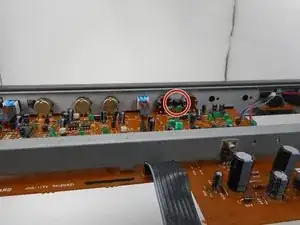
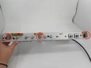
Remove the single 5.7 mm screw on the left side of the face plate.
-
Repeat the previous step on the right side of the face plate.
-
-
-
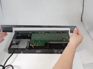
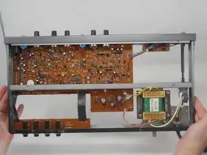
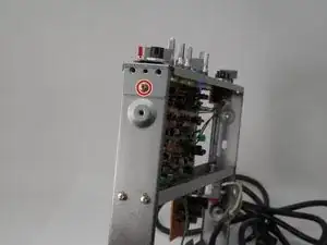
From the inside of the unit, pinch the 3 clips holding the faceplate in
-
Push the clips in and the face plate will slide off.
-
-
-
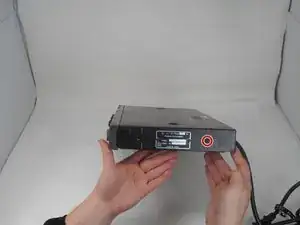
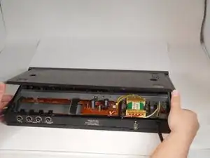
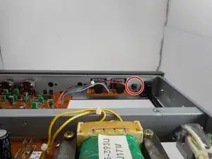
Use a Phillips #2 screwdriver to remove the single 7.8 mm screw on the left side of the bracket.
-
Repeat the previous bullet on the right side of the bracket.
-
-
-
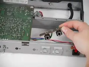
Remove the two audio jacks that are to the side.
-
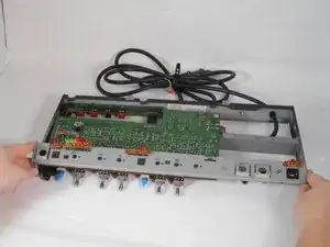
Carefully remove the face bracket by sliding it forward until it clears all dials, then lift up.
-
To reassemble your device, follow the above steps in reverse order.
Repair didn’t go as planned? Try some basic troubleshooting or ask our Answers community for help.