Introduction

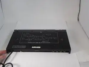
You may be experiencing power issues with your BOSS CE-300 SuperChorus that aren't resolved by simply replacing a fuse. In that case, it might be necessary to replace the power supply. This guide will walk you through the steps to replace the power supply safely and effectively in about 15-20 minutes. The tools you'll need include #2 Phillips screwdriver, soldering iron, and de-soldering pump or desoldering cable. ​

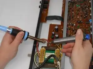
We recommend reviewing How to Solder and Desolder Connections before beginning.

  1. AK3YvuYlNhB4mJMk
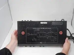
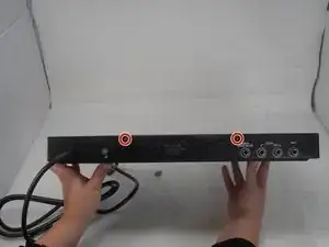
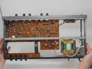
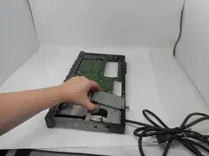
    • Use a Phillips #2 screwdriver to remove the 3 14.8 mm screws located on the left side of the CE-300.

    • Repeat the previous bullet on the right side.

  2. dqBXAFNglWAMmcPO
    • Remove the two 10 mm bolts using a Phillips #2 screwdriver.

  3. NXj2nNNcHcZPHkpP
    • On the back of the CE-300, remove the two 7.5 mm screws with a Phillips #2 screwdriver.

  4. nWI3QkYrHiBhNhvk
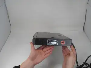
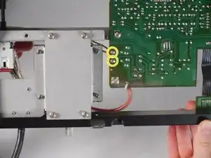
    • On the left side, remove the one 10 mm screws with a Phillips #2 screwdriver.

    • Repeat the previous bullet on the right side.

  5. TETTFHuwmHtTHMjS
    TETTFHuwmHtTHMjS
    OgyiExb1rJUS4DGJ
    • Slide the top panel away from the front.

    • Lift the panel up and off.

  6. qu2IYLRYgML41SAj
    • Remove the following screws with a Phillips #2 screwdriver:​

    • Two 7.5 mm

    • Two 10 mm

  7. CILmbQRQQNlsM1Gx
    CILmbQRQQNlsM1Gx
    cL1oZrEgMf6QYkX1
    • Lift the bottom panel up and off.

  8. iWBAgPbRqg2yklXC
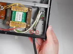
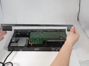
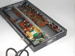
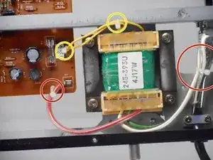
    • To remove the power supply, you have to look to the power cable.

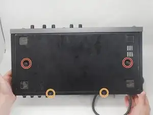
    • Remove the two 17 mm screws with a Phillips #2 screwdriver.

    • The screws are very tight. Avoid slipping with the screwdriver. Hitting the board may damage the unit.

    • Remove the white bracket pieces that come loose with the removal of the two screws.

  9. lXPK5FP1RgxcPm51
    • Push the power cable in toward the unit.

    • This allows you to visualize the solder joints on the power switch.

  10. Iw2yJcgEXioOngMq
    Iw2yJcgEXioOngMq
    AosqyDMrYrRGFLlY
    • If you are just replacing the power supply, desolder the white and green wire.

    • If you are replacing the power cable as well, desolder the white and black cable of the power cable as well.

  11. GdZMQAJXaWEQvIMG
    GdZMQAJXaWEQvIMG
    13LNu2PIdUB3myLR
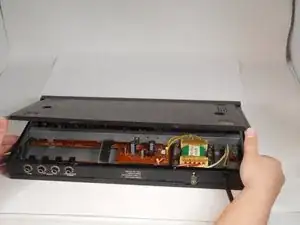
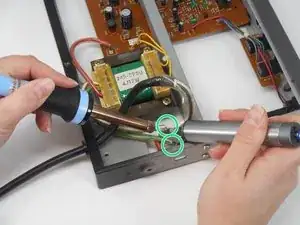
    • Cut the zipties tying the cables to the board and to the other cables.

    • Optional: The yellow cables can be removed without cutting the zipties, but it may be easier if they are cut.

  12. nmfwRxK1kLOXu62F
    • From the "bottom" of the board desolder the red cable.

  13. EIMwJXUMdggQUJfk
    • From the "top" of the board, desolder the yellow cables.

  14. WwUIPhTbCvsWMEFC
    • Remove the four 10.4 mm screws using a Philips #2 screwdriver.

  15. 3otFMKqpg2GNbrA1
    • Lift the power supply up and out.

  16. rj4vUtFnPLQOdSIJ
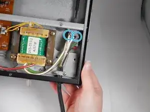
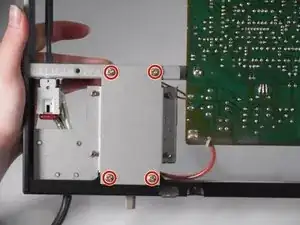
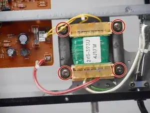
    • Optional: If your new power supply does not come with a bracket, remove the four 10 mm screws.

Conclusion

To reassemble your device, follow the above steps in reverse order.
Take your e-waste to an R2 or e-Stewards certified recycler.
Repair didn’t go as planned? Try some basic troubleshooting or ask our Answers community for help.

Haley Lansdon

Member since: 25/09/24

619 Reputation

0 comments