Introduction
If the Brother MFC-J4420DW printer does not turn on, the power supply may be defective.
Try the other options for resetting the printer first. For example, the steps in https://de.ifixit.com/Anleitung/Brother+...
These instructions do not provide information on how to repair the power supply, but how to remove it.
-
-
Disconnect the power cord of the printer
-
Open the printer as you would to access the USB port.
-
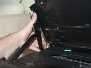
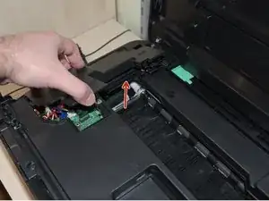
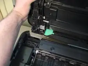
Pull out the rear end of the hood holder (see picture two). After that you can remove the top part of the hood holder.
-
Now remove the hood holder completely.
-
-
-
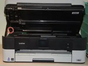
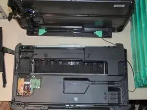
Next remove the cover on the left side of the printer (lift the right side of the cover first).
-
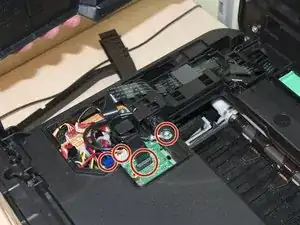
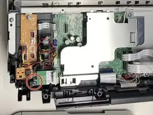
Unplug the black ribbon cable, the blue and the white plugs from its sockets and unscrew the cable which is attached with a screw (see second image)
-
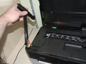
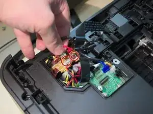
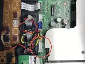
Remove the red and white plugs from its sockets as shown in picture three.
-
-
-
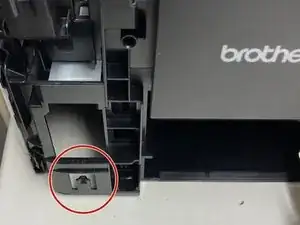
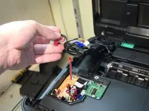
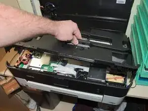
Flip the plastic part shown in picture one up to the top part of the printer
-
Now you can easily remove the top of the printer by pushing it away from the printer (not up).
-
-
-
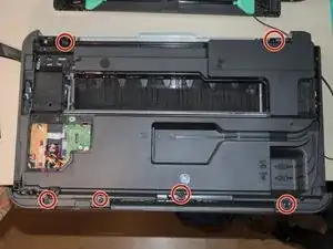
Remove the screws connecting the black plastic cover to the printer (see image)
-
Remove the cover
-
-
-
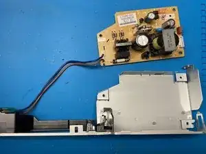
Remove the connector with the many red cables. (Already removed in the picture. The other plugs do not need to be removed.)
-


Follow the steps in reverse order to reassemble your device.