Introduction
This guide is to show you how to replace the SD card board. On the SD card board is not only the SD card reader itself, but there is also a micro switch that tells the camera if the battery door is closed. The camera will not turn on unless a signal is giving to the camera that the battery door is closed. Being that it is a small plastic switch, it is sometimes prone to breaking or having debris prevent it from working properly, stopping your camera from turning on.
The Phillips #000 screwdriver is marked as an optional tool as you can always use the JIS #000 screwdriver in its place (JIS screwdrivers won't damage Phillips head screws).
-
-
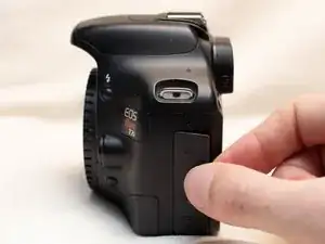
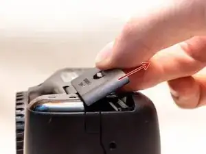
Pry open the rubber I/F terminal cap with your finger.
-
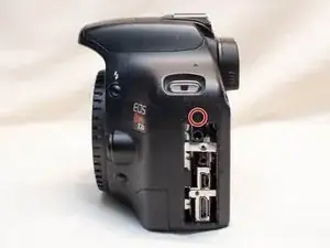
Remove the two M1.7x2.5mm JIS #000 screws that are underneath the I/F terminal cap.
-
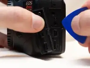
Using a plastic pick, or another thin plastic prying tool, pop off the I/F terminal cover from the camera.
-
-
-
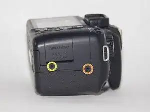
On the left side of the camera, remove the following screw:
-
One M1.7x6.0mm JIS #000 screw
-
On the right side, remove the following screws:
-
One M1.7x5.5mm JIS #000 screw
-
One M1.7x3.5mm JIS #000 screw
-
-
-
Remove the battery door.
-
Open the battery door to about a 35° angle.
-
Pull the battery door straight outwards.
-
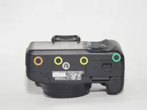
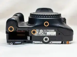
Remove the following screws from the bottom of the camera:
-
One M1.7x6.0mm JIS #000 screw
-
Two M1.7x2.5mm JIS #000 screws
-
One M1.7x5.5mm JIS #000 screw
-
-
-
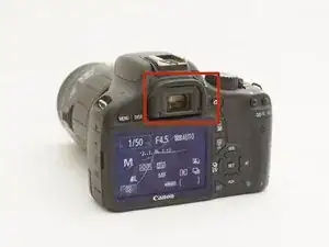
Slide the viewfinder eyepiece vertically upwards.
-
Start to pull the back cover partially off of the camera.
-
Disconnect the LCD screen ribbon cable from the main PCB board.
-
Use a plastic spudger to lift up the black locking tab.
-
Carefully pull out the ribbon cable from its connector using a pair of angled tweezers.
-
Finish pulling the back cover off of the camera body.
-
-
-
Remove the following screws from the front of the camera:
-
Two M1.7x5.5mm JIS #000 screws
-
On the bottom of the camera, remove the following screws:
-
Three M1.7x5.5mm JIS #000 screws
-
-
-
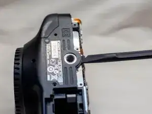
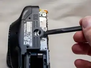
Slide a spudger tool towards the tripod mount, underneath the plastic cover.
-
Push the plastic cover up and over the tripod mount.
-
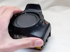
Pull the front cover off of the camera.
-
-
-
Remove the screws next to the viewfinder:
-
Two M1.7x2.5mm JIS #000 screws
-
One M2.0x8.9mm JIS #000 diopter screw
-
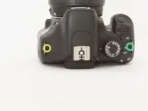
Remove the following screws from the top of the camera:
-
One M1.7x2.5mm JIS #000 screw
-
One M1.7x5.0mm Phillips #000 screw
-
-
-
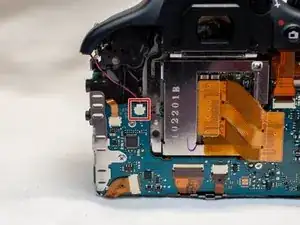
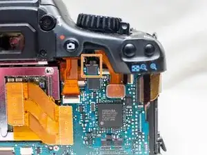
Disconnect the microphone cable from the main PCB board.
-
Position a flathead 2.5mm screwdriver between the main PCB board connector and the microphone connector.
-
Gently wiggle the flathead screwdriver back and forth until the microphone connector comes free.
-
-
-
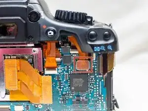
Locate the ribbon cable which connects the top cover the main PCB board.
-
Use a plastic spudger tool to carefully pry off the connector.
-
Take note of where this fiber optic cable connects to the main PCB board.
-
-
-
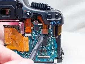
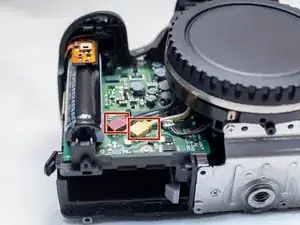
Disconnect these two cables connected to the DC PCB board.
-
Use the same method as with removing the microphone cable, except with using a flathead 3.0mm screwdriver.
-
Gently wiggle the flathead screwdriver back and forth until the connectors comes free.
-
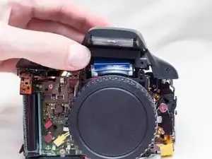
Gently lift the top cover up and off of the camera body, being careful that the loose cables do not snag on anything.
-
-
-
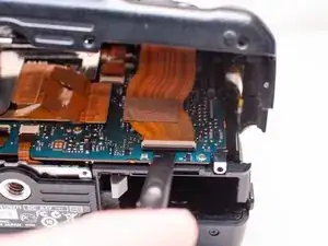
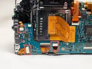
Locate these three ribbon cables located on the left side of the main PCB board.
-
Disconnect the ribbon cables.
-
Use a plastic spudger tool to carefully push up and disconnect the imaging sensor ribbon cable.
-
-
-
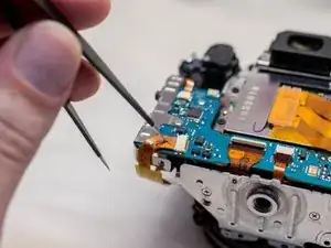
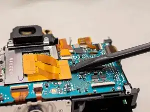
Locate the remaining seven ribbon cables connected to the main PCB board.
-
Gently push up on the plastic lock tabs to unlock each of the ribbon cable connectors. Be especially careful with the wide lock tab, as it is particularly fragile.
-
Disconnect each ribbon cable from the main PCB board.
-
-
-
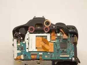
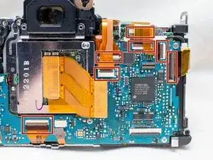
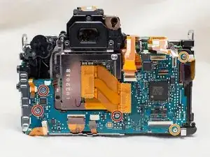
Remove the following screws on the main PCB board:
-
Three M1.7x2.5mm JIS #000 screws
-
Two M1.7x3.5mm Phillips #000 screws
-
Slide off the metal I/F terminal shield.
-
-
-
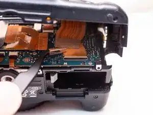
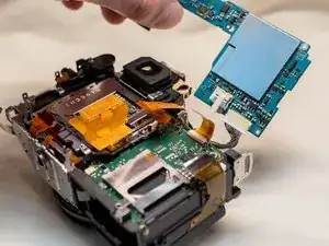
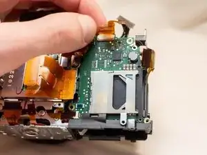
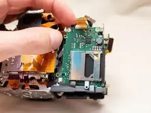
Tilt the main PCB board upwards to reveal the remaining cable connection.
-
Carefully disconnect the cable.
-
-
-
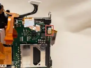
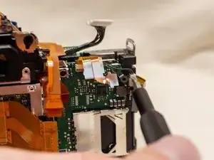
Disconnect the power cable from the SD card board using a 2.5mm screwdriver.
-
Carefully remove the ribbon cable from the SD card board using a pair of angled tweezers.
-
-
-
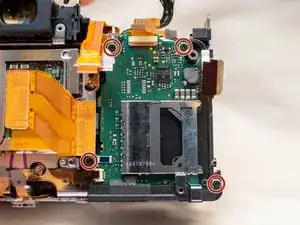
Remove the following screws from the SD card board:
-
Four M1.7x3.5mm Phillips #000 screws
-
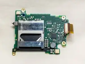
Remove the SD card board from the camera.
-
Life the top of the SD card board upwards.
-
Slide the SD card board to the right just enough for the board to clear the metal bracket.
-


To reassemble your device, follow these instructions in reverse order.