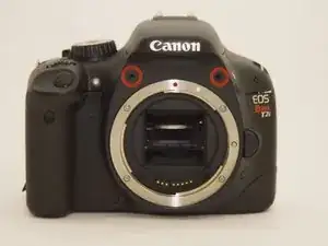
Introduction
-
-
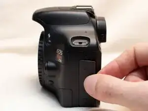
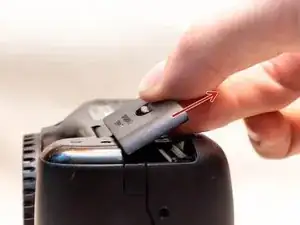
Pry open the rubber I/F terminal cap with your finger.
-
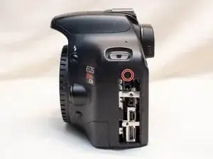
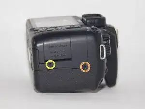
Remove the two M1.7x2.5mm JIS #000 screws that are underneath the I/F terminal cap.
-
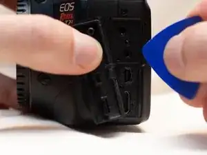
Using a plastic pick, or another thin plastic prying tool, pop off the I/F terminal cover from the camera.
-
-
-
On the left side of the camera, remove the following screw:
-
One M1.7x6.0mm JIS #000 screw
-
On the right side, remove the following screws:
-
One M1.7x5.5mm JIS #000 screw
-
One M1.7x3.5mm JIS #000 screw
-
-
-
Remove the battery door.
-
Open the battery door to about a 35° angle.
-
Pull the battery door straight outwards.
-
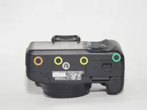
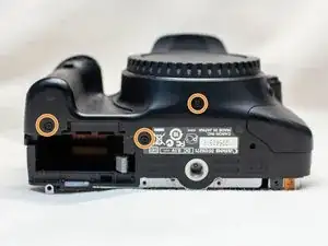
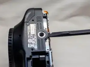
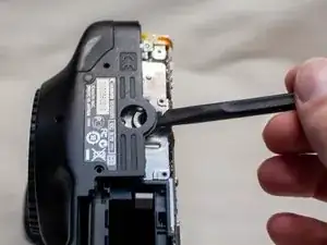
Remove the following screws from the bottom of the camera:
-
One M1.7x6.0mm JIS #000 screw
-
Two M1.7x2.5mm JIS #000 screws
-
One M1.7x5.5mm JIS #000 screw
-
-
-
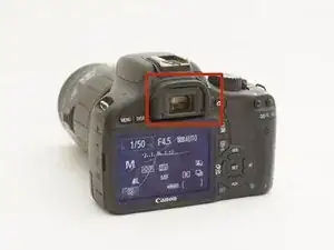
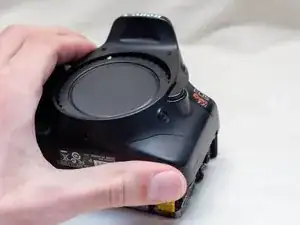
Slide the viewfinder eyepiece vertically upwards.
-
Start to pull the back cover partially off of the camera.
-
Disconnect the LCD screen ribbon cable from the main PCB board.
-
Use a plastic spudger to lift up the black locking tab.
-
Carefully pull out the ribbon cable from its connector using a pair of angled tweezers.
-
Finish pulling the back cover off of the camera body.
-
-
-
Remove the following screws from the front of the camera:
-
Two M1.7x5.5mm JIS #000 screws
-
On the bottom of the camera, remove the following screws:
-
Three M1.7x5.5mm JIS #000 screws
-
-
-
Slide a spudger tool towards the tripod mount, underneath the plastic cover.
-
Push the plastic cover up and over the tripod mount.
-
Pull the front cover off of the camera.
-
-
-
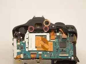
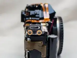
Remove the screws next to the viewfinder:
-
Two M1.7x2.5mm JIS #000 screws
-
One M2.0x8.9mm JIS #000 diopter screw
-
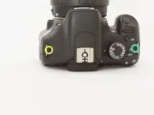
Remove the following screws from the top of the camera:
-
One M1.7x2.5mm JIS #000 screw
-
One M1.7x5.0mm Phillips #000 screw
-
-
-
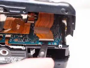
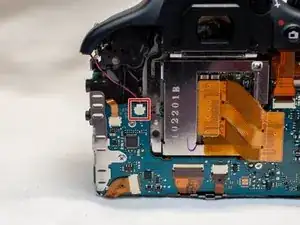
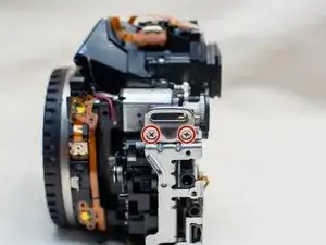
Disconnect the microphone cable from the main PCB board.
-
Position a flathead 2.5mm screwdriver between the main PCB board connector and the microphone connector.
-
Gently wiggle the flathead screwdriver back and forth until the microphone connector comes free.
-
-
-
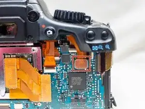
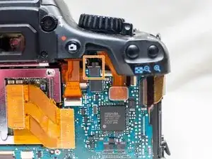
Locate the ribbon cable which connects the top cover the main PCB board.
-
Use a plastic spudger tool to carefully pry off the connector.
-
Take note of where this fiber optic cable connects to the main PCB board.
-
-
-
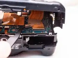
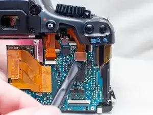
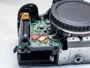
Disconnect these two cables connected to the DC PCB board.
-
Use the same method as with removing the microphone cable, except with using a flathead 3.0mm screwdriver.
-
Gently wiggle the flathead screwdriver back and forth until the connectors comes free.
-
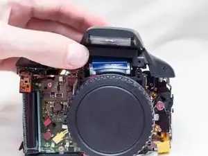
Gently lift the top cover up and off of the camera body, being careful that the loose cables do not snag on anything.
-
-
-
On the left side of the camera, remove the following screws:
-
Two M2.0x2.5mm JIS #000 screws
-
On the right side of the camera, remove the following screws:
-
Two M2.0x6.0mm JIS #000 screws
-


To reassemble your device, follow these instructions in reverse order.