Introduction
-
-
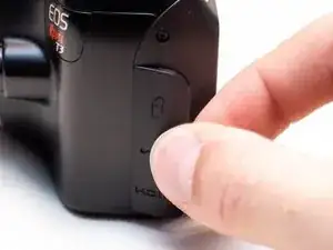
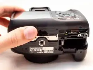
Pry open the rubber I/F terminal cap with your finger.
-
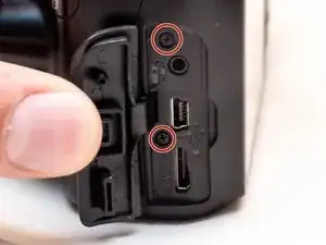
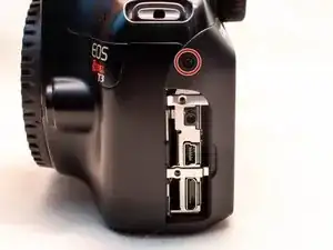
Remove the two M1.7x4.5mm JIS #000 screws that are underneath the I/F terminal cap.
-
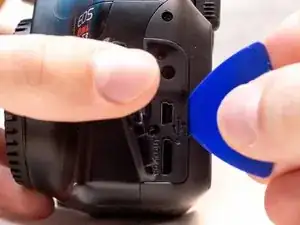
Using a plastic pick, or another thin plastic prying tool, pop off the I/F terminal cover from the camera.
-
-
-
On the left side of the camera, remove the following screw:
-
One M1.7x4.5mm JIS #000 screw
-
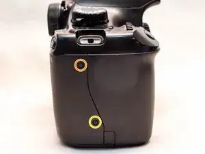
On the right side, remove the following screws:
-
One M1.7x5.5mm JIS #000 screw
-
One M1.7x4.5mm JIS #000 screw
-
-
-
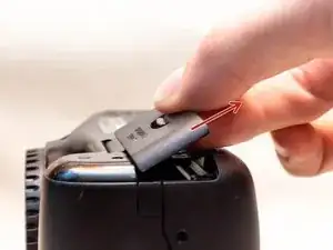
Remove the battery door.
-
Open the battery door to about a 35° angle.
-
Pull the battery door straight outwards.
-
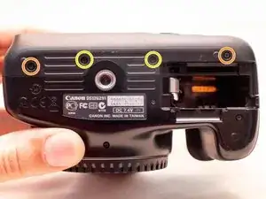
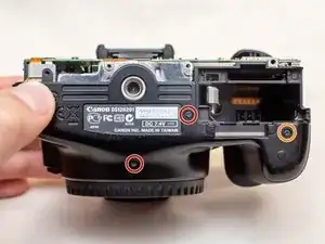
Remove the following screws from the bottom of the camera:
-
Two M1.7x4.5mm JIS #000 screws
-
Two M1.7x3.0mm JIS #000 screws
-
-
-
Carefully lift the back cover partially off of the camera.
-
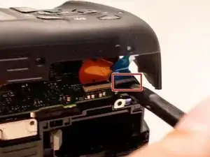
Disconnect the right most ribbon cables from the main PCB board.
-
Use a plastic spudger to lift up the black locking tab.
-
Pull out the ribbon cable from its connector using a pair of angled tweezers.
-
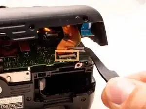
Remove the left ribbon cable using the same two steps as with the other ribbon cable.
-
-
-
On the bottom of the camera, remove the following screws:
-
Two M1.7x5.5mm JIS #000 screws
-
One M1.7x4.5mm JIS #000 screw
-
-
-
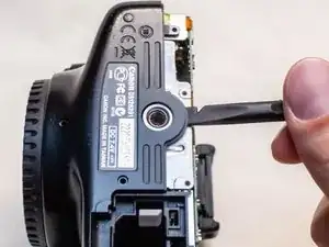
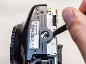
Slide a spudger tool towards the tripod mount, underneath the plastic cover.
-
Push the plastic cover up and over the tripod mount.
-
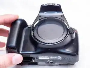
Pull the front cover off of the camera.
-
-
-
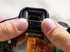
Push up and slide off the eyepiece.
-
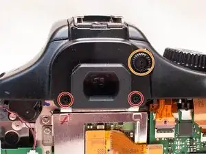
Remove the following screws:
-
Two M1.7x2.5mm JIS #000 screws
-
One M1.7x3.6mm JIS #000 diopter screw
-
-
-
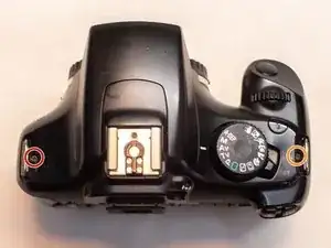
Remove the following screws on the top of the camera:
-
One M1.7x2.5mm JIS #000 screw
-
One M1.7x5.5mm JIS #000 screw
-
-
-
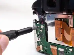
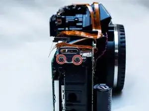
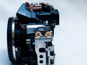
Disconnect the microphone cable from the main PCB board.
-
Position a flathead 2.5mm screwdriver between the main PCB board connector and the microphone connector.
-
Gently wiggle the flathead screwdriver back and forth until the microphone connector comes free.
-
-
-
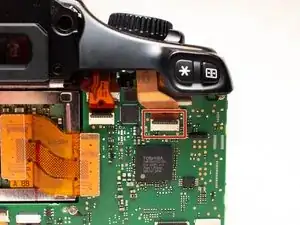
Locate the mode dial ribbon cable on the main PCB board.
-
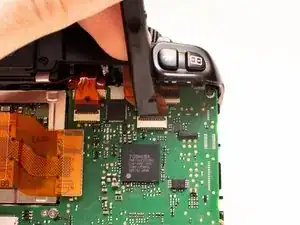
Use a plastic spudger tool to carefully lift up the locking tab.
-
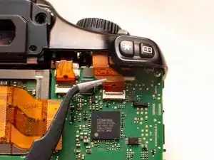
Use a pair of angled tweezers to pull the ribbon cable out of the connector.
-
-
-
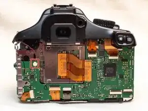
Gently lift up the top cover.
-
Set the top cover down, making sure not to pull on the cables still attached.
-
-
-
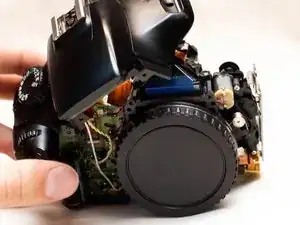
On the right side of the camera, remove the following screws:
-
Two 5.5mm JIS #000 screws
-
On the left side, remove the following screws:
-
Two 2.5mm JIS #000 screws
-

To reassemble your device, follow these instructions in reverse order.