Introduction
This guide will show you how to remove the top cover from the camera. This can be useful if you are needing to replace the top cover, needing to repair a part located inside the top cover, or to gain access to another part of the camera.
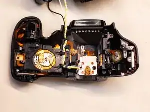
If you are wanting to either replace the entire top cover or the DC PCB assembly, you will also need to desolder the four cables connecting the top cover to the DC board.
-
-
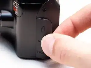
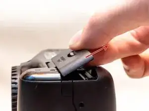
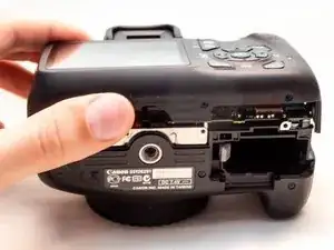
Pry open the rubber I/F terminal cap with your finger.
-
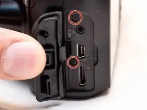
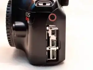
Remove the two M1.7x4.5mm JIS #000 screws that are underneath the I/F terminal cap.
-
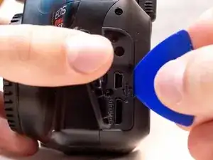
Using a plastic pick, or another thin plastic prying tool, pop off the I/F terminal cover from the camera.
-
-
-
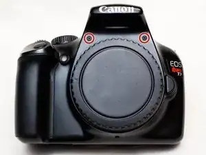
On the left side of the camera, remove the following screw:
-
One M1.7x4.5mm JIS #000 screw
-
On the right side, remove the following screws:
-
One M1.7x5.5mm JIS #000 screw
-
One M1.7x4.5mm JIS #000 screw
-
-
-
Remove the battery door.
-
Open the battery door to about a 35° angle.
-
Pull the battery door straight outwards.
-
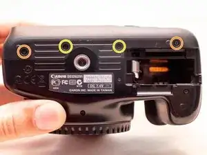
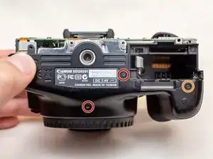
Remove the following screws from the bottom of the camera:
-
Two M1.7x4.5mm JIS #000 screws
-
Two M1.7x3.0mm JIS #000 screws
-
-
-
Carefully lift the back cover partially off of the camera.
-
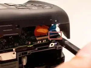
Disconnect the right most ribbon cables from the main PCB board.
-
Use a plastic spudger to lift up the black locking tab.
-
Pull out the ribbon cable from its connector using a pair of angled tweezers.
-
Remove the left ribbon cable using the same two steps as with the other ribbon cable.
-
-
-
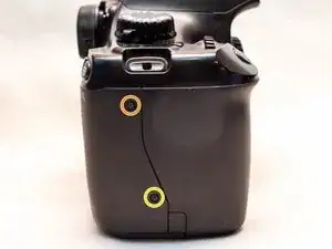
On the bottom of the camera, remove the following screws:
-
Two M1.7x5.5mm JIS #000 screws
-
One M1.7x4.5mm JIS #000 screw
-
-
-
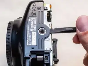
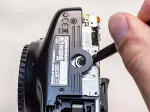
Slide a spudger tool towards the tripod mount, underneath the plastic cover.
-
Push the plastic cover up and over the tripod mount.
-
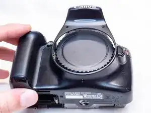
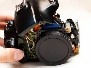
Pull the front cover off of the camera.
-
-
-
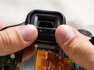
Push up and slide off the eyepiece.
-
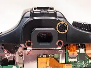
Remove the following screws:
-
Two M1.7x2.5mm JIS #000 screws
-
One M1.7x3.6mm JIS #000 diopter screw
-
-
-
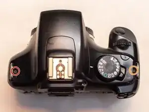
Remove the following screws on the top of the camera:
-
One M1.7x2.5mm JIS #000 screw
-
One M1.7x5.5mm JIS #000 screw
-
-
-
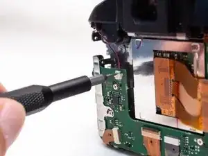
Disconnect the microphone cable from the main PCB board.
-
Position a flathead 2.5mm screwdriver between the main PCB board connector and the microphone connector.
-
Gently wiggle the flathead screwdriver back and forth until the microphone connector comes free.
-
-
-
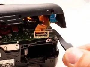
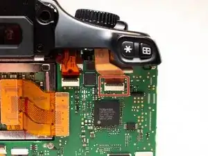
Locate the mode dial ribbon cable on the main PCB board.
-
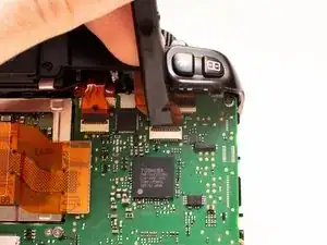
Use a plastic spudger tool to carefully lift up the locking tab.
-
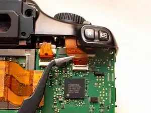
Use a pair of angled tweezers to pull the ribbon cable out of the connector.
-
-
-
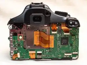
Gently lift up the top cover.
-
Set the top cover down, making sure not to pull on the cables still attached.
-

To reassemble your device, follow these instructions in reverse order.