Introduction
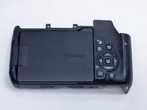
Removing the back cover is the first step for accessing most components on the camera. It can also be necessary if you need to replace the back cover itself or the LCD screen.
Note that the Phillips #000 screwdriver is marked as an optional tool as you can always use the JIS #000 screwdriver in its place (JIS screwdrivers won't damage Phillips head screws).
-
-
Before beginning, remove the battery and SD card from the camera.
-
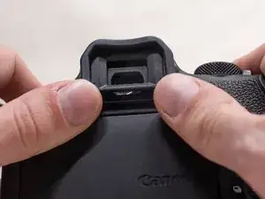
Using your thumbs, push up on the eyepiece to remove it.
-
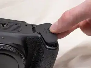
Remove the battery door.
-
Open the battery door to about a 35° angle.
-
Pull the battery door straight outwards.
-
-
-
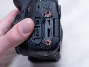
Underneath the right I/F terminal cap, remove the following screws:
-
Two M1.7x5.5mm JIS #000 screws
-
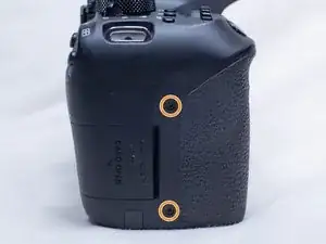
On the right side of the camera, remove the following screws:
-
Two M1.7x4.5mm JIS #000 screws
-
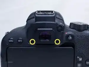
On the back of the camera, remove the following screws next to the viewfinder:
-
Two M1.7x5.0mm Phillips #000 screws
-
-
-
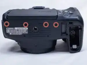
On the bottom of the camera, remove the following screws:
-
Four M1.7x5.0mm Phillips #000 screws
-
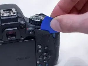
Using a plastic opening pick, partially peel up the top of the back rubber grip.
-
Carefully begin lifting the back cover up away from the camera body.
-
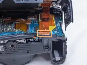
Using a plastic spudger tool, gently pry off the back cover ribbon cable from the main PCB board.
-
To reassemble your device, follow these instructions in reverse order.