Introduction
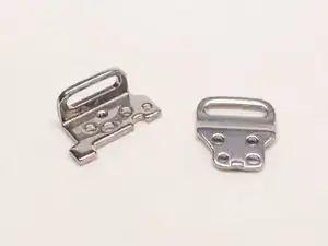
This guide will show you how to replace the two metal camera strap holders.
Note that the Phillips #000 screwdriver is marked as an optional tool as you can always use the JIS #000 screwdriver in its place (JIS screwdrivers won't damage Phillips head screws).
-
-
Before beginning, remove the battery and SD card from the camera.
-
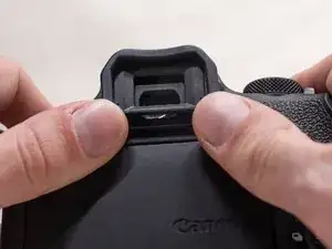
Using your thumbs, push up on the eyepiece to remove it.
-
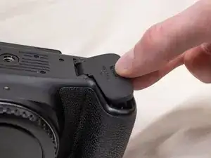
Remove the battery door.
-
Open the battery door to about a 35° angle.
-
Pull the battery door straight outwards.
-
-
-
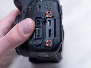
Underneath the right I/F terminal cap, remove the following screws:
-
Two M1.7x5.5mm JIS #000 screws
-
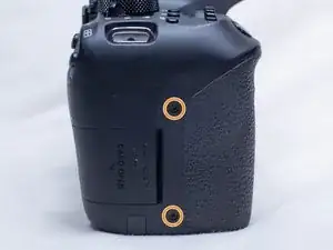
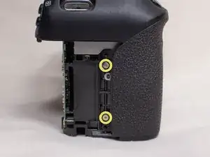
On the right side of the camera, remove the following screws:
-
Two M1.7x4.5mm JIS #000 screws
-
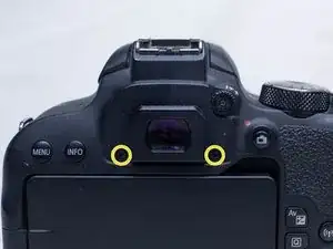
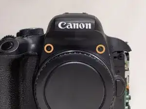
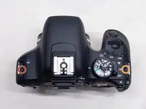
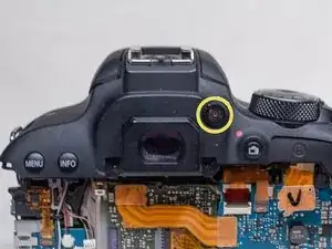
On the back of the camera, remove the following screws next to the viewfinder:
-
Two M1.7x5.0mm Phillips #000 screws
-
-
-
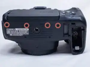
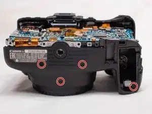
On the bottom of the camera, remove the following screws:
-
Four M1.7x5.0mm Phillips #000 screws
-
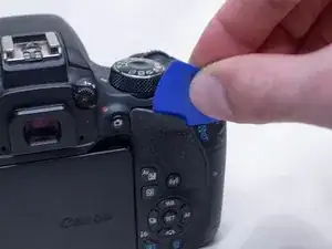
Using a plastic opening pick, partially peel up the top of the back rubber grip.
-
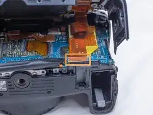
Carefully begin lifting the back cover up away from the camera body.
-
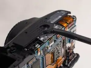
Using a plastic spudger tool, gently pry off the back cover ribbon cable from the main PCB board.
-
-
-
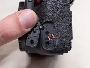
Underneath the left I/F terminal cap, remove the following screw:
-
M1.7x5.5mm JIS #000 screw
-
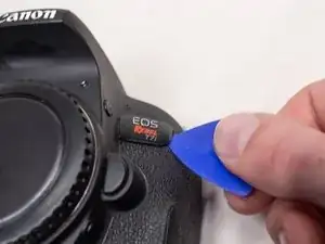
Using a plastic opening pick, peel off the front name plate.
-
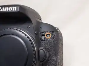
Underneath where the name plate was, remove the following screw:
-
One M1.7x5.5mm Phillips #000 screw
-
Pull off the I/F terminal cover.
-
-
-
On the bottom of the camera, remove the following screws:
-
Four M1.7x5.0mm Phillips #000 screws
-
On the front of the camera, remove the following screws:
-
Two M1.7x6.0mm JIS #000 screws
-
On the right side of the camera, remove the following screws:
-
Two M1.7x4.5mm JIS #000 screws
-
-
-
Use a plastic spudger to pry up on the bottom of the front cover and lift it over the tripod socket.
-
Pull the front cover off the camera body.
-
-
-
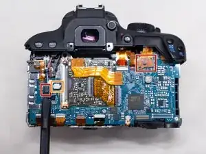
Remove these two cables from the main PCB board using a plastic spudger tool.
-
Remove the third cable using a pair of blunt tweezers.
-
Place the end of the tweezers in the small notch in the cable connector and push the connector out.
-
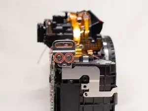
Using a pair of blunt tweezers, carefully pull out the red and yellow cables from the DC PCB board.
-
-
-
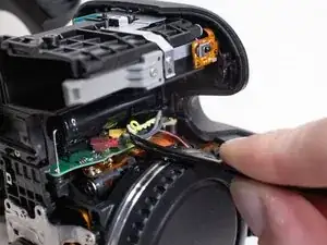
Remove the following screws from the top of the camera:
-
One M1.7x3.0mm JIS #000 screw
-
One M1.7x5.5mm JIS #000 screw
-
On the back of the camera, remove the diopter adjusting dial.
-
-
-
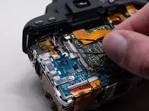
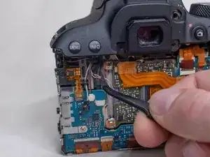
Using a pair of tweezers, move the two cables on the left side of the main PCB board so that they won't get caught while removing the top cover.
-
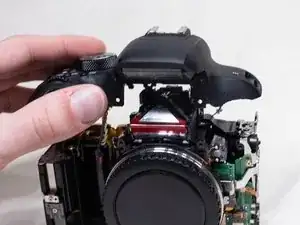
Carefully lift up the top cover off the camera body. Be careful that no cables get caught while lifting it off.
-
-
-
Remove the followings screws from the right strap holder:
-
Two M2.0x5.0mm Phillips #000 screws
-
Remove the followings screws from the left strap holder:
-
Two M2.0x5.0mm Phillips #000 screws
-

To reassemble your device, follow these instructions in reverse order.