Introduction

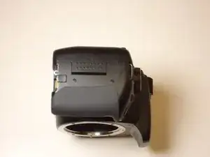
After long term use, it is possible that the shutter button on your camera needs to be replaced. While replacing this component may be somewhat involved, it can restore functionality to your camera.

  1. eVNaGnROZKlM5UPX
    • Place the camera upside down, and position it to where the back of the camera is visible.

  2. B6oKTtSBscpBBZgQ
    • Pull the orange tab to the right to release the primary battery.

  3. LShBoBNhsd3GPMsj
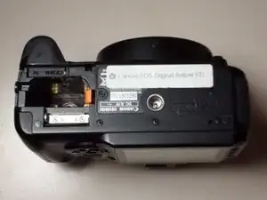
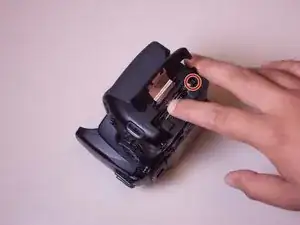
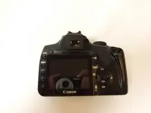
    • To remove the secondary battery, reposition the camera to where the display screen is facing upwards.

    • Place your finger inside the empty battery compartment and pull away from the camera on the ridged battery tab.

    I have the rebel xti as well, and have the same issue, and i have 2 new primary batteries, and 1 new secondary battery, and 1 new charger, yet the camera, still will not turn on. So, if not the battery or the battery charger, what could be the problem? Ty

    Rich Irons -

    I had no idea my camera had a second battery!

    Terri -

  4. WZKtsgBtBwH6c5QJ
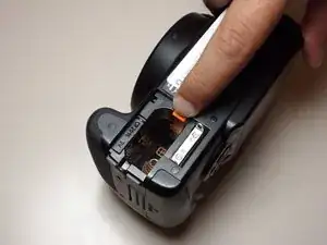
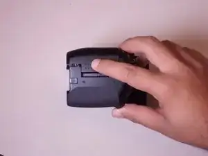
    • Place the camera on its side with the soft touch grip facing up and the top of the camera facing right.

  5. IJfkvVOxfSbMWfpP
    • Slide the memory card door in the direction of the arrow engraved on the camera.

    • Once the door has slid open to its full position, lift up on the door.

  6. EouHaNMKYtujTXih
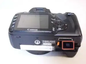
    • With the door open, push down the small black plunger next to the CF slot. The CF card will disengage from the slot and be ejected far enough that you can grasp it between thumb and forefinger and remove it from the slot.

    • The plunger will stay in its depressed position until a CF card is again inserted in the slot.

  7. chsDUW4eW1iT6bgo
    • Remove the three black M3x4mm JIS #000 screws on the bottom of the camera.

  8. U5vt6jtap6ZyV5p3
    U5vt6jtap6ZyV5p3
    SAFMaSJQY5QBRNfM
    • Remove the two black M3x6mm JIS #000 screws from the right side of the camera.

  9. 56PyANZVbsMDHDBt
    • Remove the two M3x5mm JIS #000 screws on the side of the camera opposite to the hand grip.

  10. 2rFAMPqxTM6KiRGL
    • Remove the following screws located in the memory card slot:

    • Two M3x2mm JIS #000 screws

  11. wggcmjLLBGTxQnTe
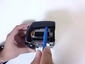
    • Gently pry off the back casing.

    • Before completely removing the back casing, be sure to disconnect the single ribbon cable running from the motherboard to the LCD display.

    • Use a spudger to lift the tab on the ribbon cable's ZIF connector.

    • Gently pull the ribbon cable out of the connector.

  12. d5aFlhSOvXFAZngS
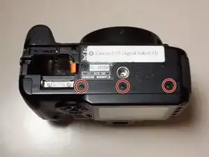
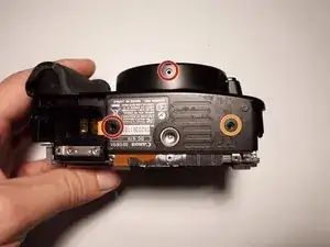
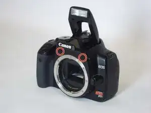
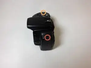
    • Remove the following screws from the bottom of the camera:

    • Two M3x4.5mm JIS #000 screws

    • One M3x3mm JIS #000 screw

  13. NLGkGMRINDQa36EI
    • Remove the following screws from the front of the camera:

    • Two M3x6mm JIS #000 screws

  14. rvIGB1A12pta5w2Z
    • Gently pry off the front casing.

    • There are no ribbon cables to remove for this portion of the disassembly.

    You forgot to mention removing the 2 screws just above the lens mount on the front.

    3cinema com -

  15. BmvAd1ChRY2SPP6P
    BmvAd1ChRY2SPP6P
    lTFDQMC1aKNwsncH
    xLutRa3jJsOmhboy
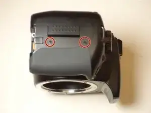
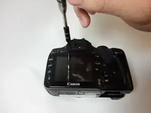
    • Remove the following screws from around the viewfinder:

    • One 10mm JIS #00 diopter screw

    • Two M3x6mm JIS #00 screws

  16. HibhHQHZv6HygFKP
    HibhHQHZv6HygFKP
    u245ZVkpUAuG1MLq
    s16s2lFm5eAf53an
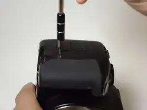
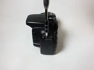
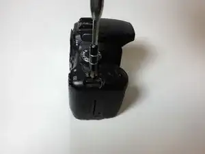
    • Remove the following screws on each side of the camera under the strap hooks:

    • One M3x5mm JIS #00 screw

    • One M3x4.5mm JIS #00 screw

  17. kBCET6yBlPwvEYQG
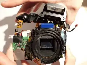
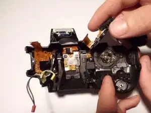
    • Separate the top casing from the electrical components enough to expose the wire harnesses that will need to be disconnected.

    • Ensure to remove the casing gently. There are several wire harnesses connecting the motherboard to components on the casing.

  18. HOymVIuqhhFIlcFG
    • Unplug the yellow connector located on the top of the camera.

  19. LyfoQMjliolyvQMv
    • Disconnect the red connector located by the USB port.

  20. O1C1HHXAcREANUBp
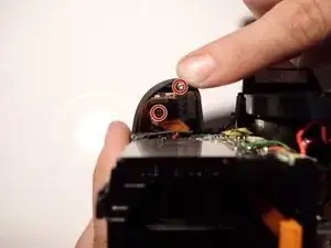
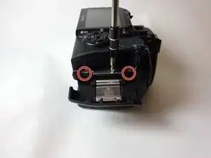
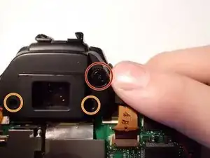
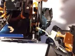
    • Use a JIS #00 screwdriver to remove the two silver 4 mm screws from underneath the shutter button.

  21. 5ZGblNcJhMXwHUqh
    5ZGblNcJhMXwHUqh
    6IwxnB4bciGIJHAy
    UsCKYbxHmCpLRfub
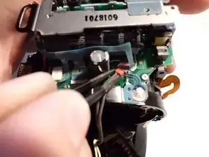
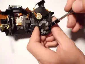
    • Use a JIS #00 screwdriver to remove the 3mm screws from the plate under the shutter button.

    • Place the components off to the side without removing any ribbons.

    • Be careful as ribbon cables are fragile and may rip easily.

  22. WYGjtpeYpcXQToC3
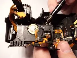
    • Use a 1.5mm flat head bit to remove the c-clip from underneath the snapshot button by pushing against the open side of the pin.

Conclusion

To reassemble your device, follow these instructions in reverse order.

Luis Calle

Member since: 30/08/15

416 Reputation

0 comments