Introduction

This guide provides an outline of how to replace the flash assembly on the Canon PowerShot A80 camera. The flash assembly is a retractable light bulb fixture that emits a quick burst of background light. With prolonged use, the flash assembly's light bulb can burn out, necessitating replacement for the camera to function correctly.

To prevent any damage to the camera, ensure that the environment is completely dry and free of any water that could accidentally spill onto the sensitive camera electronics. Additionally, make sure the camera is turned off to avoid any harm to the camera's motherboard (refer to step 15).

Exercise caution in Step 5 when removing the lid from the main body. The mylar cable attached to the top lid is fragile and may become damaged or disconnected. Apply gentle and careful pressure when removing the lid.

When removing the flash box in Step 18, use caution and remove it with a rubber glove or a screwdriver with a rubber handle. This precaution will prevent electric shock in case the capacitor inside the flash has not been discharged.

  1. 4t5IJfQ2ioegABlH
    • Remove the three Phillips #00 screws from the bottom of the camera.

  2. aR65oqdcViu3r2Iy
    aR65oqdcViu3r2Iy
    vLvvGNvMn5aXM1Qt
    • Open the door to the CompactFlash memory card slot by sliding it towards you and swinging it open.

    • Remove the memory card if it is still in the camera.

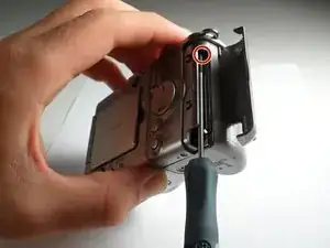
    • Use the Phillips #00 screwdriver to remove the single screw underneath the memory card slot door.

  3. SURPSLeKSpd6UB5A
    • Remove the Phillips #00 screw located inside the top of the memory card compartment.

  4. 3PFx2iGC5knujAsc
    3PFx2iGC5knujAsc
    i1nMdFtuyTkwiyQx
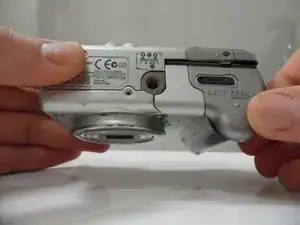
    • Open the battery compartment door at the bottom of the camera by sliding the latch to the right and then sliding the door down.

    • Remove the batteries from the compartment.

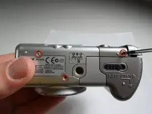
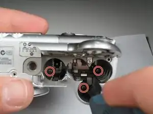
    • Remove the three Phillips #00 screws located inside the battery compartment.

    • The screw on the left is longer than the other two.

  5. OSXk1DvAjYhCE1XC
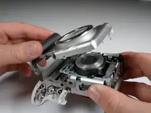
    • Remove the top lid of the camera.

    • Be cautious of the fragile mylar cable that connects the lid to the main body of the camera.

    • Removing the lid takes a little force. Do this gently. There may be a snapping sound.

    • The door to the memory card compartment will be freed and should be removable now.

    • In other versions of this camera, there is a tab that secures the top from the wrist strap. If yours has this, you won't be able to completely separate the top until you have removed the top screw in Step 8.

    The upper screw from Step 6 must be removed first, ( also fixing top lid )

    micsch4 -

  6. k2sP1RFFioqqXdfD
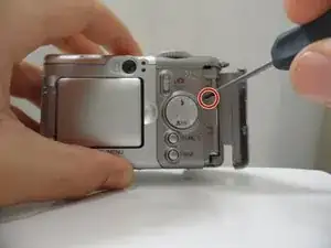
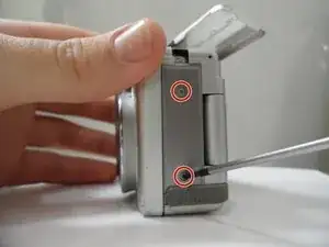
    • Remove the two Phillips #00 screws from the side of the camera.

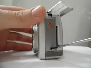
    • Open the small rubber door below this screw that covers the connectors.

  7. OPsHMkTbBnNjHfbU
    OPsHMkTbBnNjHfbU
    UNqkyWtBRISMbMrL
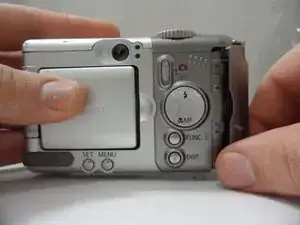
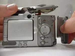
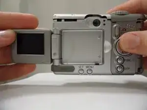
    • Open and pivot the LCD screen to its widest open position.

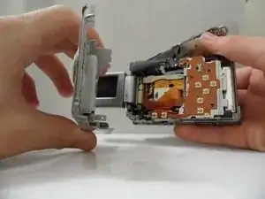
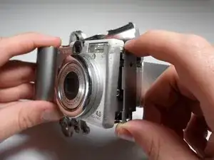
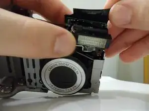
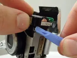
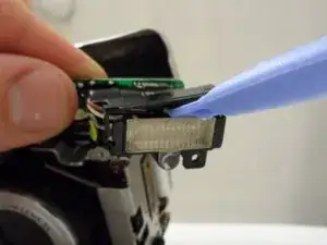
    • Remove the rear cover by pulling it straight away from the body of the camera.

    • When reassembling the camera, remember to replace the screws in the same location from which you removed them. Otherwise, you may damage the camera.

  8. Wgkh1SW5Lji5IpWt
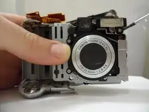
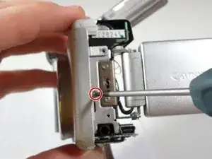
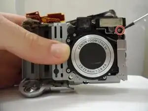
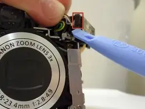
    • Using a Phillips #00 screwdriver, remove the 3.3 mm long top screw located on the side of the camera. This screw holds the side panels and the front cover together.

    • The side panel may get stuck on the internal wires, so gently wiggle this panel loose.

    When returning this panel insert a slip of paper so that you can shepherd the tab past the wires, then pull it out when the panel is correctly in place.

    Richard -

  9. QyjEEVXofhK2v1ZY
    • Gently remove the side panel by pulling it away from the camera.

    • The side panel may get stuck on the internal wires, so gently wiggle this panel loose.

  10. JiSZEhgBuQVQUuGc
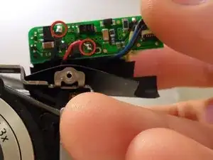
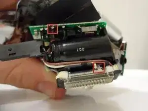
    • Using the Phillips #00 screwdriver, unscrew the 2.4 mm long screw that holds on the front panel underneath the side panel.

  11. 4SjuEQnRPXvyKBfD
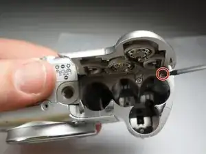
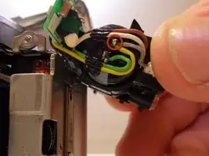
    • Underneath the battery cover there is a 3.8 mm screw in the corner. Using the Phillips #00 screwdriver, remove this screw.

  12. ESfKr24sE6gEq1BL
    • Gently pull up on the front cover to remove it from the body.

  13. dj4VoEqWXqTdmKTr
    • Unscrew the 3.8 mm screw under the flash housing.

  14. d4IwxpkGfIFnZeon
    • Lift up black cover.

    • Black cover is attached to the top of the capacitor with adhesive.

  15. wCYMaIahD1AEVZtQ
    • If the entire flash housing needs to be replaced...

    • Unsolder the black and red wires from the back of the circuit board behind the flash.

  16. ZN2xtSOZcwTFmTCS
    ZN2xtSOZcwTFmTCS
    X1NBiYgjDPqGlUQA
    • Use the opening tool to unclip both sides of the black cover on top of the flash

  17. swCV5QVpAPYZyGV2
    • Use the opening tool to lift off the black flash cover.

  18. OjZ4qKXkIkPQxI41
    • If the flash needs to to fixed...

    • Unsolder the brown wire from the circuit board.

    • The piece of metal that attaches these parts will have to be bent back.

    • Make sure the capacitor is discharged before these steps are attempted. Do so with a screwdriver with a rubber handle.

  19. CC2grVa3FJGmZtSa
    • Unsolder the gray wire attached to the capacitor.

    • This is the last wire that connects to the flash.

Conclusion

To reassemble your device, follow these instructions in reverse order. Remember to re-solder any wires that were unsoldered.

ryne contreras

Member since: 28/01/11

141 Reputation

0 comments