Introduction

Follow this step by step installation guide for replacing the motherboard on your Canon Powershot SD700 IS camera.

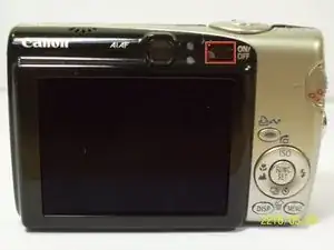
In order to make the process easier please view our more indepth guide on taking off the camera's casing in the LCD replacement guide.

  1. qYKF5GXMXCgO5D5O
    • Turn off the camera by pressing the power button above the LCD screen.

  2. tuRtbvBEwOERpACe
    • Remove the two small screws on the bottom of the camera using a Phillips #00 screwdriver.

  3. UJyBXyDKiI5Jqh3J
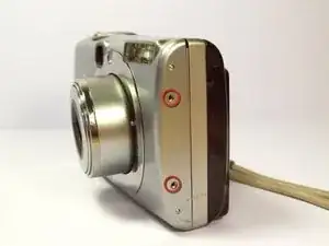
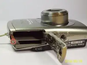
    • Use a Phillips #00 screwdriver to remove the two small screws on the right side of the camera.

  4. Qs2evXXk4gNhZM5q
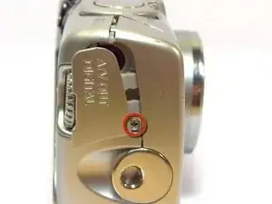
    • Use a Phillips #00 screwdriver to remove the screw on the left of the camera under the A/V out digital label.

  5. YBbt6BODIFR5p5dM
    • Use a Phillips #00 screwdriver to remove the screw on the bottom of the camera near the battery and memory card slots.

    • This screw will be longer than the rest of the screws.

  6. Nk1plWGxIQHAJwE4
    • Remove the front, back, and side casings from the camera and set to the side.

  7. XoNH5GZDK6cZwQYI
    • Detach the LCD and backlight.

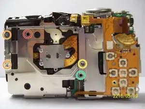
    • Remove the larger screw.

    • Remove the two smaller sized screws.

    • Remove the small screw.

    • Remove the small screw.

    On my camera (SD700) there were no screws where yellow circles are. There was a total of 5 screws in this step which should be easy to spot. It is important however to keep track of which screw goes where as there is 3 different size screws in this step.

    Mike -

  8. VAXpcXOrNrlVTQAT
    • Remove the two screws near the the tripod mount using a Phillips #00 screwdriver.

    One of the 2 screw locations in diagram is wrong. One screw goes through flex circuit but the other screw goes in the hole in top left of picture closest to LCD assembly.

    Mike -

    I should clarify - the second screw goes in the hole just above and left of tripod lug hole.

    Mike -

  9. adZbtt3DZKVyAvRT
    • Remove the screw next to the shutter on the top of the camera with a Phillips screwdriver.

  10. qbaOQGx3hOVvbjup
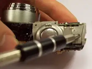
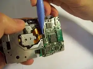
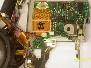
    • Remove the orange ribbon cable by lifting the ZIF connector attached to the ribbon with a spudger.

    Need to remove another screw from lower right corner of main board cover (partially hidden by flex circuit) before cover can be removed.

    Mike -

  11. M4PGP2Y23KaWSAZi
    M4PGP2Y23KaWSAZi
    BPFvlNaTa6NoQcvu
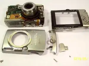
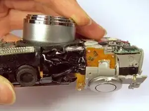
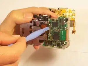
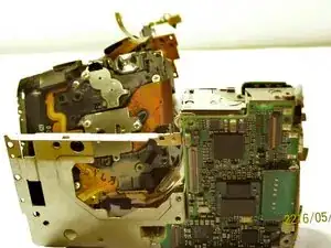
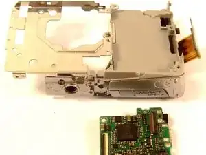
    • Carefully lift the shutter along with the ribbon connected to it. This will remove the casing around the motherboard.

  12. uolDYksNuwvnOwdy
    uolDYksNuwvnOwdy
    J5wAqyn4jJFRxEvW
    5glLGrSVgwn2BwXb
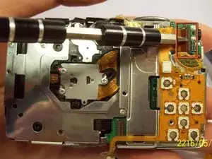
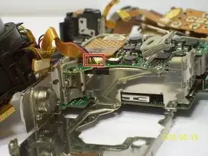
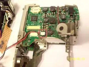
    • With the motherboard casing detached, remove the short orange ribbon by lifting the ZIF connector with a spudger or other plastic opening tools and slide the ribbon out. Detaching this ribbon will disconnect the side of the camera containing the motherboard from the rest of the camera.

  13. VltukXMDiSSTucAC
    VltukXMDiSSTucAC
    qxO6ta4Ig3WUGwvb
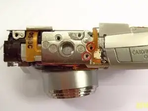
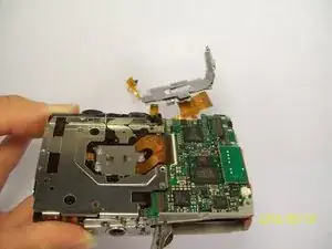
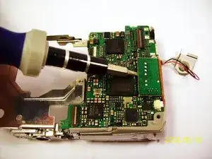
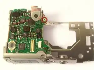
    • Disconnect the wires that are attached to the motherboard.

    • Remove the film by lifting it gently from the motherboard.

  14. AhkfgHn4liOqZWMF
    • Remove the last wires connected to the motherboard by gently lifting upwards.

  15. a1Wo4J2bc5DYiAg4
    a1Wo4J2bc5DYiAg4
    V4LYHkIMkSSCsAAN
    • Use a spudger to gently lift the circuit board.

  16. IFVVOHcNoOJRRH3u
    IFVVOHcNoOJRRH3u
    vCGErAK3eOZKBt6f
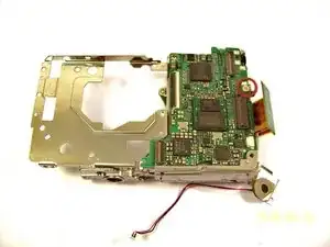
    • Remove the screw using a Phillips #00 screwdriver.

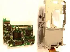
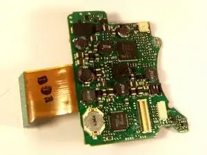
    • Gently lift the motherboard away from the case.

  17. Qm3ofNnbrhyGrEBu
    Qm3ofNnbrhyGrEBu
    FiETgOgDQxYgCIeT
    • Remove the screw.

    • Once the screw is removed, you can remove the board.

Conclusion

To reassemble your device, follow these instructions in reverse order.

Kenneth Lim

Member since: 07/04/11

61 Reputation

0 comments