Introduction
The Phillips #000 screwdriver is marked as an optional tool as you can always use the JIS #000 screwdriver in its place (JIS screwdrivers won't damage Phillips head screws).
-
-
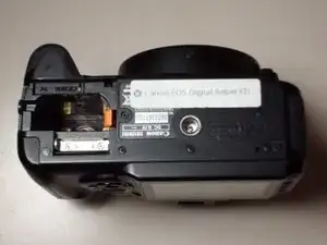
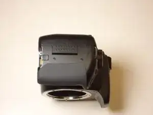
To remove the secondary battery, reposition the camera to where the display screen is facing upwards.
-
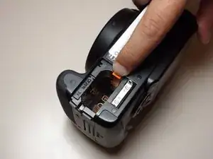
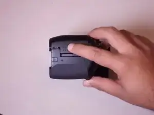
Place your finger inside the empty battery compartment and pull away from the camera on the ridged battery tab.
-
-
-
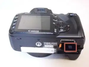
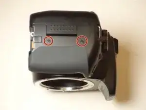
Place the camera on its side with the soft touch grip facing up and the top of the camera facing right.
-
-
-
Slide the memory card door in the direction of the arrow engraved on the camera.
-
Once the door has slid open to its full position, lift up on the door.
-
-
-
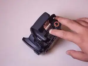
With the door open, push down the small black plunger next to the CF slot. The CF card will disengage from the slot and be ejected far enough that you can grasp it between thumb and forefinger and remove it from the slot.
-
-
-
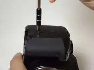
Gently pry off the back casing.
-
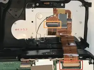
Use a spudger to lift the tab on the ribbon cable's ZIF connector.
-
Gently pull the ribbon cable out of the connector.
-
-
-
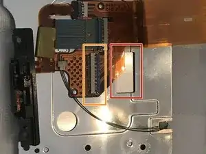
Remove the ribbon that connects the back housing to the camera logic board. Remove the cable by flipping the black part 90 degrees up away from circuit board. Pull the ribbon cable out carefully.
-
Remove the screen ribbon cable from the connection. Follow the same procedure from the last step.
-
-
-
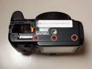
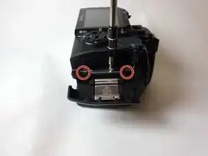
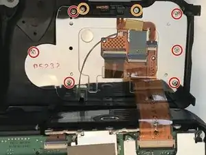
Remove the following screws from the inside of the back cover:
-
Six Phillips #000 screws around the metal backing
-
Two Phillips #000 screws by the plastic piece to remove proximity sensor
-
-
-
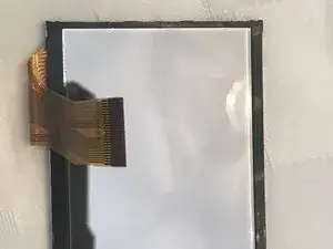
Carefully remove the old screen from the display board. There are 4 metal clips that hold the LCD screen to the backlight. Carefully bend them slightly outwards and the screen should come out. Pull the ribbon cable out with the screen.
-
-
-
Carefully thread the ribbon cable from the replacement LCD screen through the hole in the metal casing. The ribbon cable from the screen has to go on top of the existing cable. You may need a spudger or toothpick to get the new cable on top.
-
Connect the ribbon cable from the new screen to the connection socket.
-


To reassemble your device, follow these instructions in reverse order.