
Introduction
This guide will show you how to properly disassemble the camera in order to safely remove and replace the LCD screen of your Canon Vixia HF S10 camcorder.
The LCD screen of the camera displays the settings of the lens, as well as the photos and/or videos taken on it. If used long enough with high brightness, the screen may become discolored and leave a "burned in" image on it. You will know if you have screen burn if you see things like the camera ISO and shutter speed left on the screen when you use other features of the camera.
While following the guide make sure you are being careful, as breaking any wires or connections may prevent the screen or other parts of the camera from working. Also check to make sure the camera is fully powered off before starting , to remove the battery, and unplug the camera from the charger.
-
-
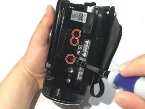
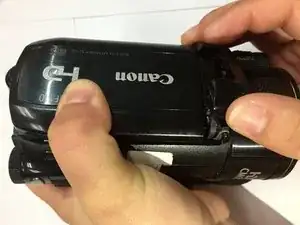
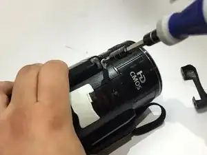
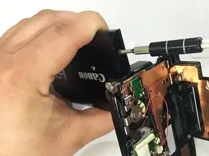
Turn the camcorder upside down and remove the three 4 mm Phillips #00 screws securing the black plastic case.
-
-
-
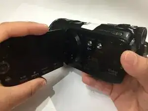
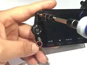
Flip open the LCD screen.
-
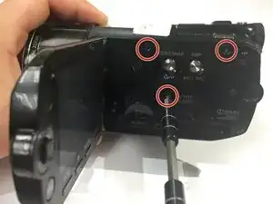
Remove the three 4 mm Phillips #00 screws securing the black panel plastic case.
-
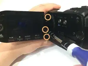
From the inner corner in between the panel and the LCD screen, remove the two 2.5 mm Phillips #00 screws and the single 4 mm Phillips #00 screw.
-
-
-
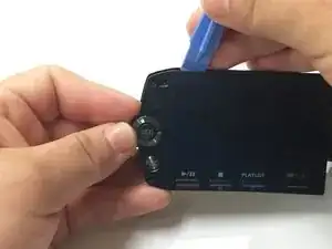
Using your fingers, remove the black plastic covering.
-
Remove the 2.5 mm Phillips #00 screw located at the top of the hinge.
-
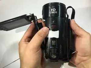
Remove the panel from the base of the camcorder.
-
-
-
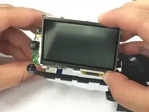
Use a Phillips #00 screwdriver to remove the 2.5 mm screw from the right side of the plastic case surrounding the LCD screen.
-
Remove the two 2.5 mm Phillips #00 screws from the front of the plastic case.
-
-
-
Use a plastic opening tool to pry off the plastic case surrounding the LCD screen.
-
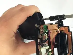
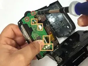
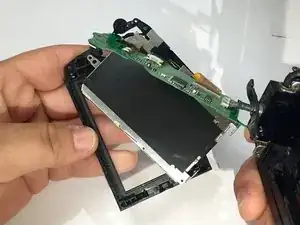
Use a Phillips #00 screwdriver to remove the two 2.5 mm screws from the motherboard on the back of the LCD screen.
-
Disconnect the cables from the motherboard. One of the connectors is soldered. For more details on desoldering connectors, take a look at this guide.
-
Gently pull off the motherboard from the LCD screen.
-
To reassemble your device, follow these instructions in reverse order. Take your e-waste to an R2 or e-Stewards certified recycler.
2 comments
Not enough detail to be really useful. For example,doesn't mention how to reconnect the ribbon strip. To be fair, no one else says how to be sure it's connected properly either.
John -
The trick to reconnecting the orange ribbon is to bend back the ribbon from its natural position so it sticks out a bit then to put the plastic body almost back in position, leaving the gap open like a partially opened book. The ribbon and socket should be almost aligned. The gap should be just enough to see in and poke about with a small tweezers. I needed a decent light and glasses to carefully align the ribbon into its receptacle. I used a small fine pair of tweezers to push (not grab!) the ribbon into place. Make sure the ribbon is correctly inserted and aligned then carefully gently flip the securing clip with the the tweezer and moving along the clip push it gently to secure the ribbon. Dont push too hard, it wont help! Next carefully manipulate the shell over the main body making sure it is aligned at back of the camera with the screw holes all lined up. Put just a couple of screws in to stabilize the loose shell then pop in the battery to check operation of the screen and buttons.