Introduction

If your Casio CTK keyboard (model 3200) has an LCD screen that is not working or is broken in any way, use this guide to replace the screen.

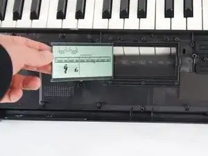
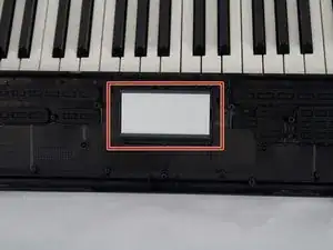
The LCD screen will relay information of what the keyboard is doing to the user visually so you are able to see what key is being pressed, if there is a sound playing, what modifier is active, etc. It sits on the main board and through the main board, it receives the signals that tell it which parts of the screen to light up. This means it is integral to put the screen back correctly and in the same orientation as it was before.

  1. YQkj3MGWuFWmsPIF
    YQkj3MGWuFWmsPIF
    CYcMlOoSQV63RS3b
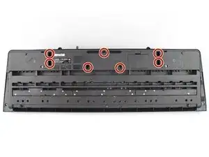
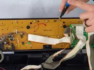
    • Remove the seven 10 mm Phillips #1 screws on the underside of the keyboard that secure the center front panel.

  2. UTKTBCAxLCFwxoMT
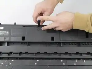
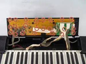
    • Flip the keyboard over and remove the central panel on the front and place it above the keyboard.

    • Make sure not to sever or strain any connections between the yellow-colored main board and the central panel.

    • If the panel is not easily removable, make sure all the screws are removed from the back.

  3. alOBbygv3UawbfL3
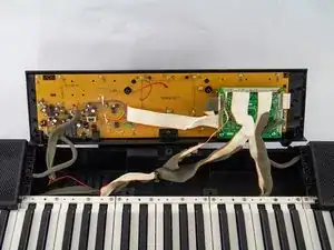
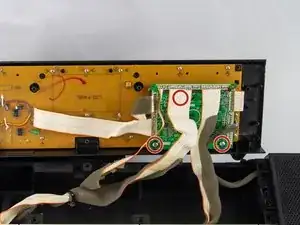
    • Make sure you are not putting too much strain on the wires that connect the yellow board to the rest of the piano.

  4. E1RCT3dL424ScjsE
    E1RCT3dL424ScjsE
    ZxvOJwjp2IuBIkNr
    • Remove the three 12 mm Phillips #2 screws from the green PCB.

    • This step will require you to move some of the motherboard's wiring. Make sure not to separate any of the connection points.

  5. lIoLkceiCh4knFed
    lIoLkceiCh4knFed
    h3kaLFHcFh3yRVhi
    • Remove all twenty-three of the 10 mm Phillips #1 screws from the yellow circuit board.

  6. qvtQTfnKdsRJHCnt
    • The board is now able to be removed from the center front panel. Carefully remove the board, making certain not to break the board or any of the components attached to it.

    • Make sure the center front panel is facing down for this step, as the keys will come loose from the front of the panel.

  7. mEGGjiHXIY5uI2VU
    mEGGjiHXIY5uI2VU
    pDQgf3nEUZDlS2fc
    • Carefully lift out the LCD screen.

    • If the screen has not been taken off before it might seem like it is glued to the board; this is normal.

  8. 3QMhgogHZLpuHcYl
    3QMhgogHZLpuHcYl
    JNFNRoZPlk6AFFcH
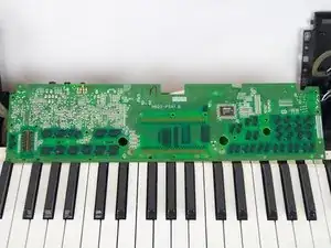
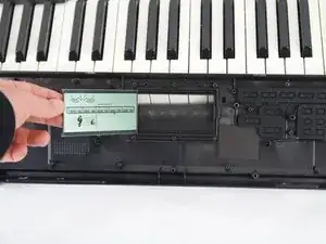
    • Place your new screen face down into the center panel. Lay the screen exactly as shown in the first image, then let it fall over and land face down into place.

    • Make sure the screen is right side up. This will ensure that all of the electrical components line up correctly when the main board is re-attached to the center panel.

Conclusion

To reassemble your device, follow these instructions in reverse order.

Will Wright

Member since: 23/10/24

369 Reputation

0 comments