Introduction
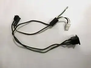
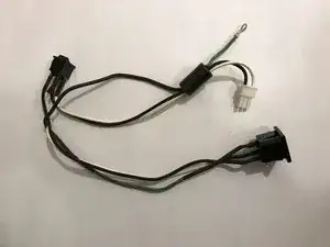
The mains wiring harness is located behind the inner cover of the toner compartment, including an IEC C14 power socket and the main power switch, and connects the external power cable to the power supply board mains input.
-
-
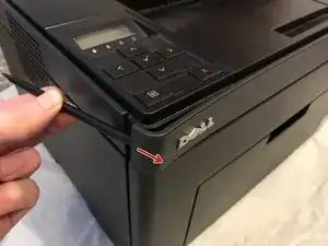
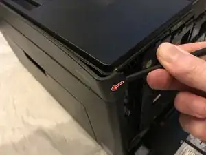
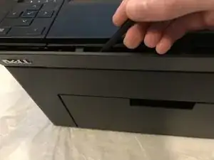
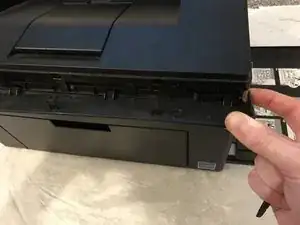
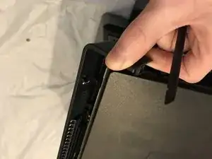
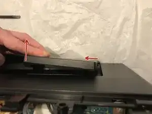
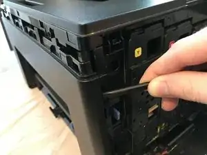
Insert prying tool behind each end of the plastic strip. Pry outwards to unclip and pull the ends forwards away from the printer.
-
Note - Unclipping the right-hand end requires opening the toner cover for access.
-
-
-
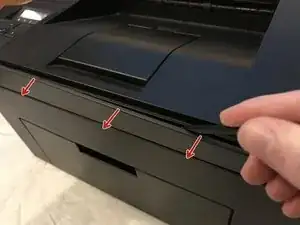
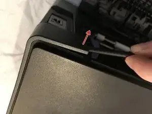
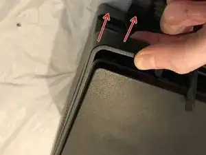
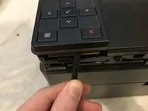
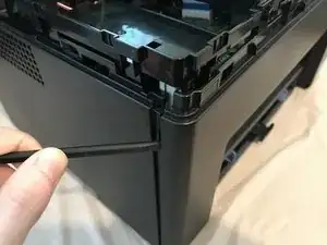
Insert prying tool between the front band and top cover of the printer, and pry forwards to release the clips holding the top edge in place.
-
-
-
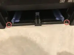
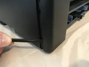
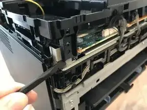
Unclip the back end of the plastic trim by prying away from the printer back panel.
-
Pull the trim piece towards the back of the printer.
-
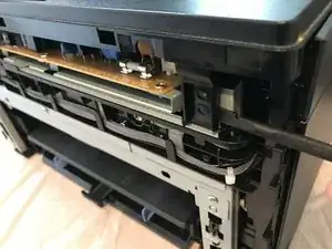
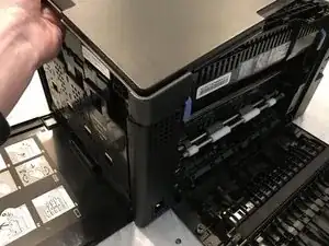
Tilt the top edge away from the printer and lift away to remove.
-
-
-
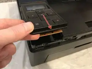
Pry up front edge of the control panel module to unclip.
-
Lift up front edge and pull module forwards slightly to unhook rear edge.
-
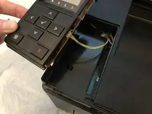
Pull out cable connector to unplug the display/ control panel module.
-
-
-
Remove the front lower flap by carefully bending in the middle and pulling out the locating pins one end at a time.
-
-
-
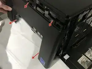
Unclip the three clips along each end of the front cover by prying outwards and forwards with a prying tool as shown.
-
-
-
Slide out the bottom edge away from the printer and pull the front cover down away from the top edge to remove.
-
-
-
Pull the top cover brackets forwards off the metal frame and lift up to loosen the front edge of the top cover.
-
-
-
Pry the top cover clip off the locating peg at the back of the printer, and lift up the top cover corner.
-
-
-
Pry apart the back edge of the top cover and the back cover of the printer to unclip the top cover.
-
-
-
Lift up the top cover from the control panel corner, pulling towards the back right-hand corner.
-
Note - The top cover should unclip from the back corner with the corner/side piece still attached.
-
-
-
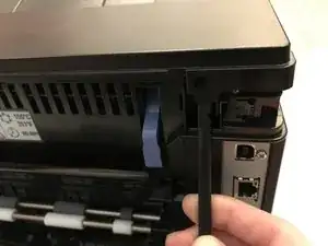
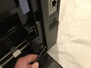
Unclip the back edge of the side cover by prying away from the printer back panel.
-
Pull the top of the side panel away from the printer.
-
Lift up the printer from underneath to release the bottom clips, and the side panel drops away from the printer.
-
-
-
Pull out the connector for the rear cover sensor from the power supply board.
-
De-route the light pink coloured pair of sensor cables and remove from the wiring harness.
-
-
-
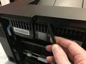
Unclip the rear cover opposite the de-routed cables by prying away from the rest of the printer using a prying tool.
-
The rear cover can now be removed from the printer.
-
-
-
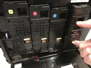
Remove the four toner cartridges from the printer.
-
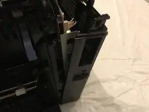
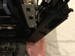
Slide the outer cover towards the back of the printer to pull out the locating pins and remove.
-
-
-
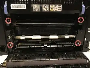
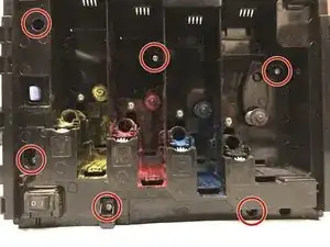
Remove the six 7mm phillips screws holding the toner compartment inner cover to the printer.
-
-
-
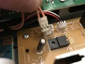
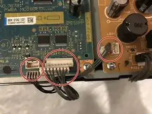
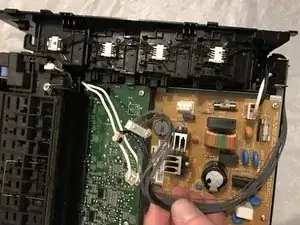
Unplug the three connectors for the toner control/ data cables (two from the control board and one from the power supply board) by pulling the connector up from the board.
-
De-route and remove these cables from the front cable guide.
-
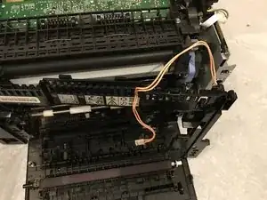
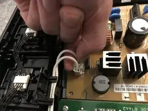
Unplug the fuser unit power cable by squeezing the top of the retaining clip and pulling the connectors up from the power supply board.
-
De-route the fuser unit power cable from the cable guide on the back of the inner toner cover.
-
-
-
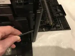
Push down on the power switch retaining bracket to release the cover from the switch.
-
Pull the toner compartment inner cover away from the printer, taking care to lift the cover over the springs passing through it (otherwise these may drop more toner dust), to remove the toner inner cover assembly.
-
-
-
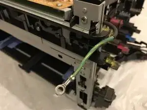
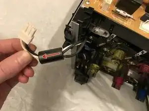
Pinch the top of the retaining clip on the mains input plug and pull up from the power supply board to unplug.
-
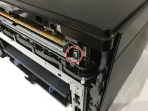
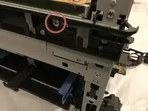
Unscrew the 5mm M4 phillips screw attaching the earth cable to the chassis.
-
De-route the earth cable from around the front of the printer.
-
-
-
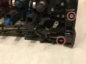
Unscrew the two 7mm phillips screws holding the mains input connector bracket to the printer.
-
Pull the mains input connector away from the printer.
-
-
-
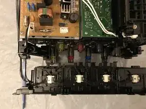
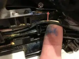
To remove the wiring near the mains input socket, lift up the black & white cables over the retaining clip.
-
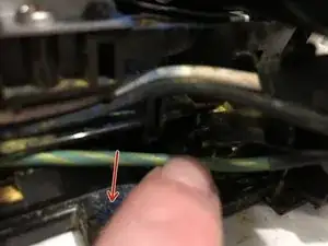
Pull the earth cable down from underneath its retaining clip.
-
Repeat this for each cable restraint along the cable route at the bottom of the printer.
-
De-route the wiring from the power supply board down to the power switch.
-
-
-
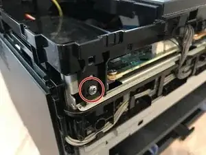
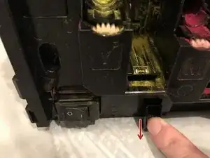
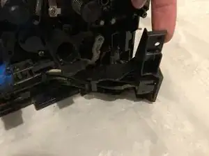
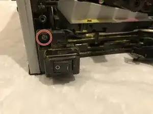
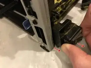
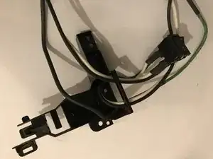
Unscrew the 7mm phillips screw holding the power switch bracket to the printer.
-
Pull the bottom of the switch bracket away from the printer.
-
Twist the bracket clockwise while gently pulling away from the printer to unclip and remove.
-
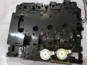
Unhook any remaining routed cables near the switch and remove the wiring harness assembly from the printer.
-
-
-
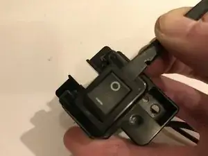
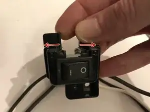
Push in the retaining clips on one side of the switch and pry that side out from the bracket.
-
Slightly pull apart the open end of the bracket and push the switch forwards through the bracket to release the clips.
-
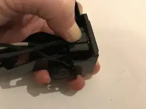
Lift the open end of the bracket over the cables to remove from the wiring harness.
-
-
-
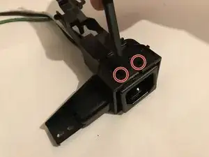
Press in the larger retaining clip and push out that side of the mains input connector slightly through the bracket.
-
Push in the retaining clips on the opposite side of the connector using a pointed prying tool (or small screwdriver etc.)
-
-
-
Feed the wiring and switch through the mains input connector bracket to separate the wiring harness from the bracket.
-


To reassemble your device, follow these instructions in reverse order.