Introduction
This guide will show you how to replace the cooling fan for your Dell B130. The cooling fan keeps the internals of the laptop cool so it can run efficiently. Some problems that arise when this is not functioning correctly is when the computer will turn off suddenly or it is running very slow.
-
-
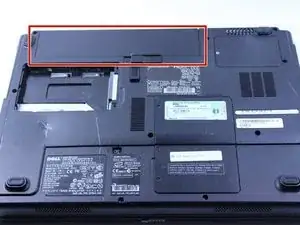
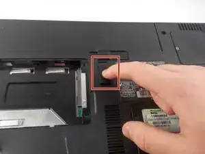
Push the tab from the battery, downwards to unlock the battery.
-
The tab should be in the position next to the unlocked indicator.
-
-
-
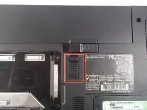
Now, push the other tab (the one right under the battery) from right to left.
-
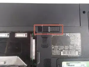
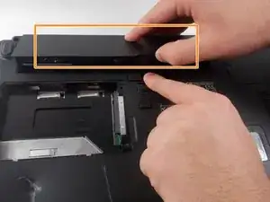
Now the battery will be loose; lift the battery up and out of the computer.
-
-
-
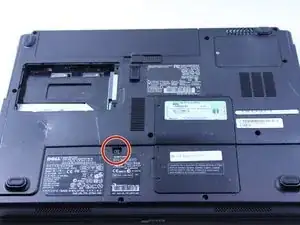
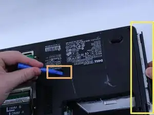
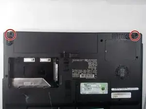
Remove the 8mm screw
-
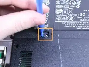
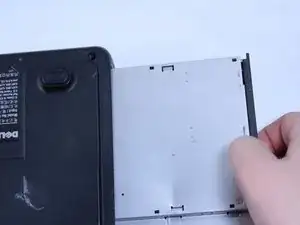
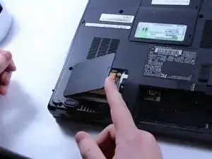
Use the plastic opening tool to push out the disk drive.
-
Pull the disk drive out with the opposite hand.
-
-
-
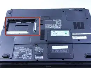
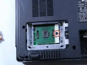
This particular computer is missing its hard drive.
-
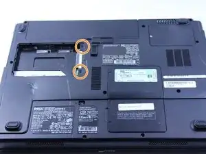
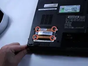
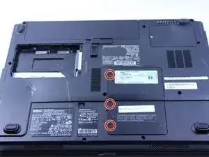
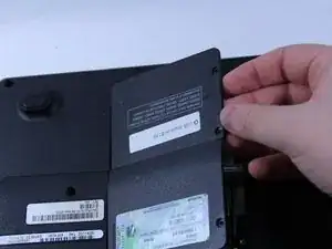
Remove the two screws.
-
Remove the plastic cover by lifting from the groove as indicated.
-
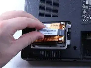
Remove the hard drive from the computer by lifting up and out.
-
-
-
Put down the computer and open up the screen.
-
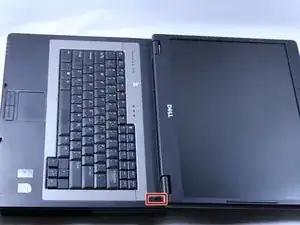
There is a long piece of plastic underneath the screen that you will have to remove.
-
-
-
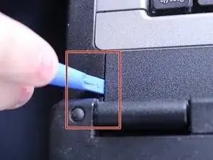
Insert the plastic opening tool into the little slot.
-
Lift up gently and remove the plastic cover.
-
-
-
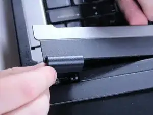
Lift keyboard up slightly and you will see the keyboard connection.
-
This black tab has to be lifted up to remove the keyboard.
-
Put your finger underneath the tab and pull back gently as indicated.
-
You can now remove the keyboard.
-
-
-
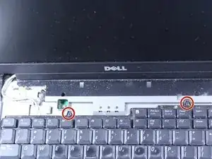
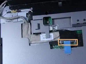
After opening the panel, you will see two cable connections attached to the screen.
-
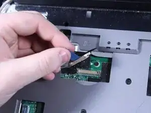
Identify the one with blue tape this is the display connector that needs to be removed.
-
-
-
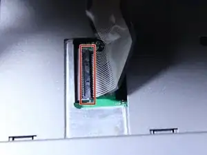
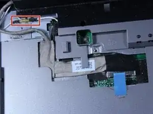
Locate the second connector next to the one removed in the previous step, This connector does not have blue tape but still needs to be detached. To remove it safely hold both sides of the connector firmly. Pull it straight apart avoid twisting or pulling at an angle to prevent damage.
-
-
-
Locate the two 6mm screws positioned directly beneath the screen. Use a Phillips #1 screwdriver to remove both screws. Keep the screws in a safe place, as they will be needed for reassembly.
-
-
-
Close the computer and flip it over so that the back is facing up.
-
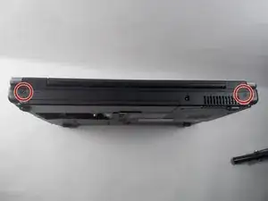
Remove the two 6mm screws that are behind each of the screens pivot points. Use a Phillips #1 screwdriver to remove these screws.
-
Open up the screen and now it can be lifted up and off of the computer.
-
-
-
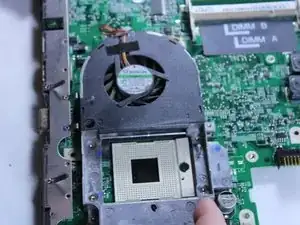
Use a flat head screwdriver to turn the screw one quarter turn into the unlock position.
-
Remove the CPU.
-
-
-
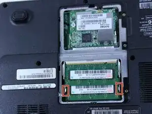
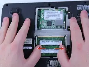
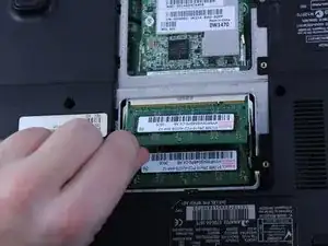
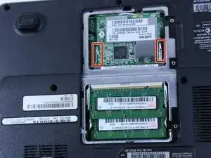
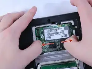
To remove the RAM, push outward against the metal brackets.
-
The first RAM will pop up so you can just pull it right out.
-
Repeat the first step again to remove the second RAM chip.
-
Installation is the reverse of removal.
-
-
-
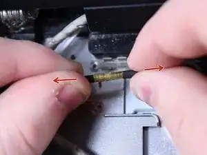
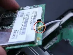
To remove the wire, hold the wireless chip firmly and pull the connection straight up off of the chip.
-
-
-
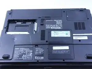
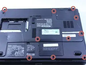
Use a Phillips #0 screwdriver to remove the twelve 8mm screws from the bottom of the laptop. Keep the screws organized to avoid losing them.
-
-
-
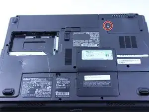
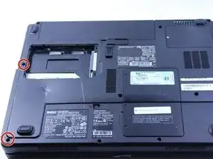
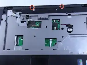
Turn the laptop over so that the keyboard side is facing up, then locate and remove the two 4mm screws positioned just below where the screen would be using a Phillips #0 screwdriver.
-
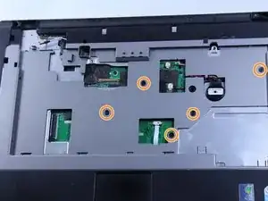
Remove the five remaining 6mm screws. Be sure to keep track of these screws, as they will be needed for reassembly.
-
-
-
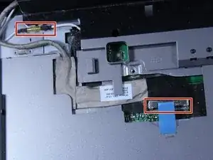
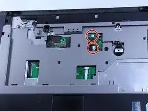
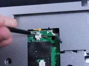
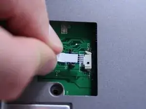
Disconnect this connection before proceeding.
-
Use tweezers to grab the small black connector and pull it straight back carefully. Avoid pulling on the wire directly, as this may cause damage to the connection.
-
You can now disconnect this wire.
-
-
-
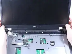
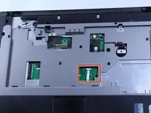
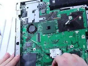
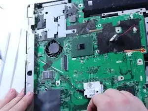
Lift and remove the entire cover/frame from the top of the motherboard. Gently pull up to detach it without using excessive force
-
Remove the motherboard by pulling it upward and sliding it to the right. Be careful not to damage any remaining connectors or components. If the motherboard feels stuck, double-check that all screws and cables have been disconnected.
-
-
-
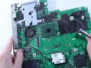
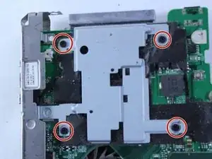
Remove these four 4 mm screws.
-
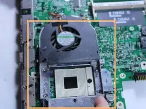
Turn the motherboard over and lift the fan up.
-
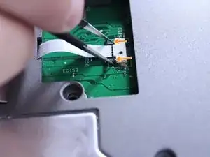
Disconnect the wire that connects the fan to the motherboard by pulling up gently.
-
You can now remove the fan.
-


To reassemble your device, follow these instructions in reverse order.