Introduction

This guide shows how to remove or replace the main board electronics in a Dewalt DCN21PL Nailer.

  1. SNCupeVSVYMU4VvF
    SNCupeVSVYMU4VvF
    AYfDHcpBYvMiUtWv
    • Before you begin the repair, remove the battery from the device.

  2. 1emeokHf12Le1F5y
    1emeokHf12Le1F5y
    JUIThwjRowlO4Ntr
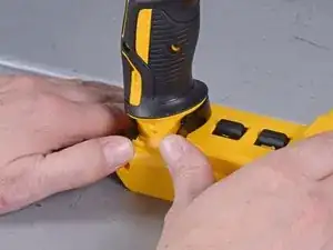
    • Use a T10 driver to remove the four screws securing the bottom half of the casing.

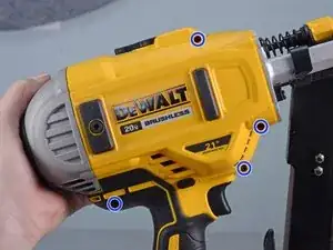
    • Remove the four T10 screws securing the top half of the casing.

  3. BviMMOiJLJCYWSjD
    • Use a T10 driver to remove the screw securing the magazine to the base.

  4. HBYeF21vNAXHSM6b
    HBYeF21vNAXHSM6b
    kxJOK1Xave4JCBuT
    • Pull the magazine down and away to unlatch and release it from the nailer.

  5. RGue5F1oJFcQk2mk
    RGue5F1oJFcQk2mk
    FRMeckCmggvbb2e3
    kPwZuKYsmlYZJOIO
    • Use a T15 driver to remove the framing hook retaining screw.

    • Remove the hook.

  6. kf6P1kXrHyjLTNNg
    • This step may require a lot of force.

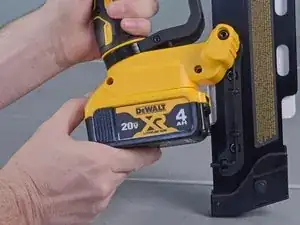
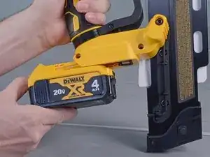
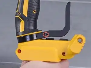
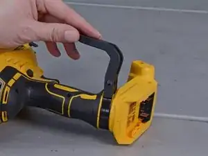
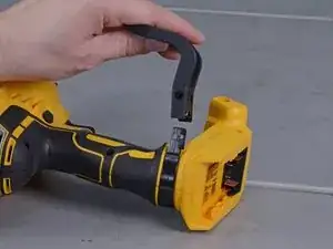
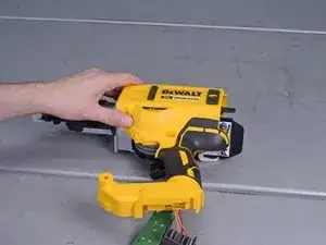
    • Use your two thumbs to firmly spread the metal hook clamp apart while slowly pushing it forward off the handle.

    • When this clamp is being removed, it has a tendency to launch off of the handle after you release tension.

    When putting back this part be careful because it will pinch your hand

    albert jara -

  7. gXHYi3VG5BRObe4i
    gXHYi3VG5BRObe4i
    q3vjSJcVjBgEO32q
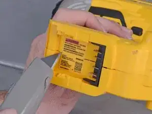
    • Use a sharp blade to slice the label underneath the battery mount to disconnect the two halves of the case.

    • Always cut away from you or others around you.

  8. brnfJ3S2wiMENZfh
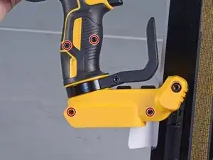
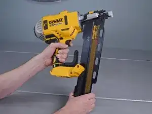
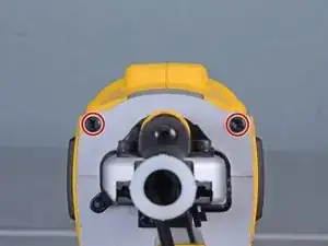
    • Use a T20 driver to remove the two screws securing the two halves of the case to the front assembly.

  9. pMJBqQCHP6SEJBQB
    pMJBqQCHP6SEJBQB
    3igGbGu5bUrclNDC
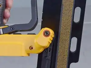
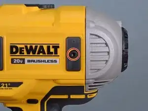
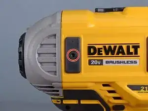
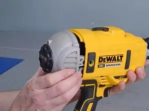
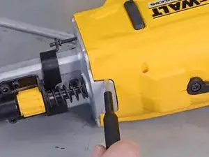
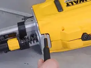
    • Use the provided 3.5 mm hex key to remove the two return system bolts on either side of the nailer.

  10. ovutayNVskCD2hBv
    ovutayNVskCD2hBv
    iepRD4BYYjpCdRLX
    WEpEkiodKfK5jGmC
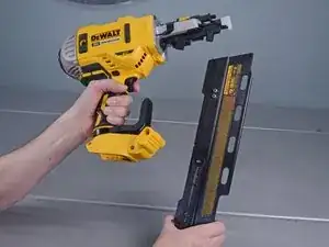
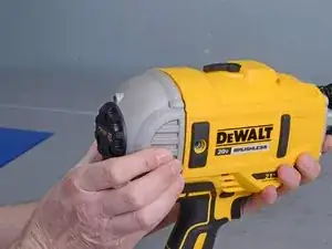
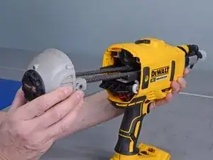
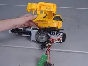
    • Grab the end cap and slide the return system assembly out of the back of the nailer to remove it.

  11. eiNBSvUxEgwA4AHU
    eiNBSvUxEgwA4AHU
    YxUTXjfSUIYyfOFO
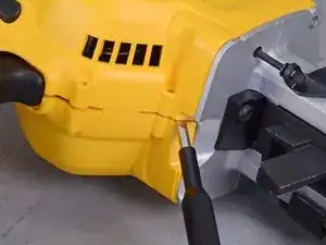
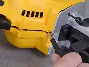
    • Use a small flathead screwdriver in the gap between the two halves of the casing near the trigger to pry the two halves apart.

  12. bisrEvDXbcBgkoeN
    bisrEvDXbcBgkoeN
    15cqMBiMWrXfixSF
    • Use a small flathead screwdriver near the top seam to continue prying the case apart .

  13. J4NrDqfFlbgNZUtk
    J4NrDqfFlbgNZUtk
    jNgOoIPZBFaTtEb5
    • Once loose, lift up to remove the right half of the clamshell case.

  14. CXWQVnOKZCwUKm1O
    CXWQVnOKZCwUKm1O
    l4UdXZRkPX2S4LcK
    • Remove the plastic lens cover.

  15. JZx2sIyApBScHLRA
    JZx2sIyApBScHLRA
    RHr6tAZjpdcRr5IF
    iQImVN1VtIsPfLZs
    • The two switches and four detent springs are only held in place by the plastic casing, so they may fall out when you remove the board—this is fine.

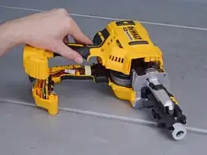
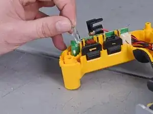
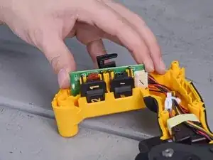
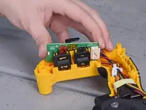
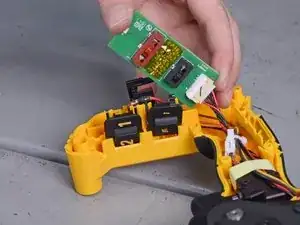
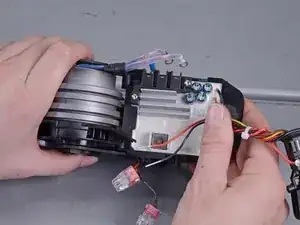
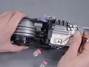
    • Grasp either side of the main circuit board and slowly pull it up and out of the slot in the casing.

    • Reassembly tip: note the correct location and orientation of the two switches and their detent springs.

  16. RSITISOIOuZGn2Ce
    RSITISOIOuZGn2Ce
    YSpCLfZo2yWW5IqN
    • Pull up on the trigger lock to remove.

  17. P6mtEowkQMqTQlyF
    P6mtEowkQMqTQlyF
    X1ffjkBDEMHBo3Ql
    • Flip the nailer over.

    • Remove the remaining clamshell casing.

  18. UJCiD3nSMqgjBtYK
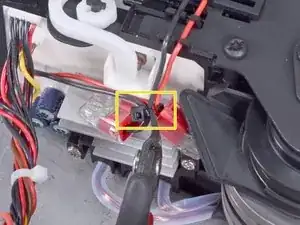
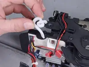
    • Use wire snips to cut the small black cable tie securing the four main board wires together.

  19. EsVYLTKMqQojAoVe
    EsVYLTKMqQojAoVe
    TlXUQN4JjexYTDot
    • Pull the white plastic actuator straight up off its axle to remove.

  20. jZTAK6cppuCO3be5
    jZTAK6cppuCO3be5
    KIyTptnE2mVOJmfT
    XqMGZMKvBiUT5pxo
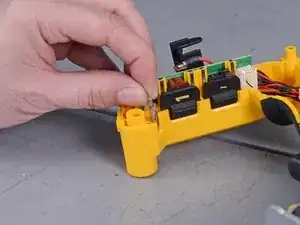
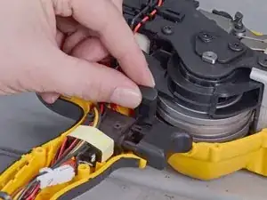
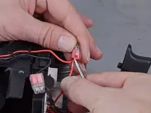
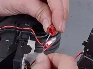
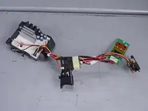
    • Insert the point of a pick tool into the push-in connector's inlet hole, which has the main board wire plugged into it.

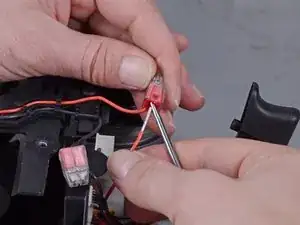
    • With the pick tool still inserted, pull the red main board wire out of the push-in connector.

    • Make sure you choose the inlet that connects to the main board, not the solenoid.

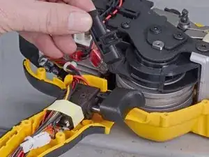
    • Repeat this same process for the black wire and other push-in connector.

  21. GyMYhpWXyaoyN5e4
    GyMYhpWXyaoyN5e4
    kVBcJxA5udikRvDY
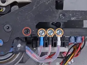
    • Use a T20 driver to remove the following screws:

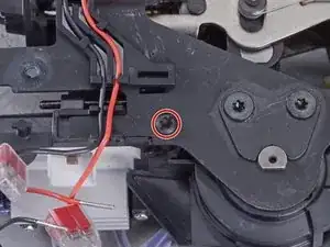
    • Two 15 mm-long board retaining screws, one on either side.

    • Three 10 mm-long motor wire screws.

  22. cQY6knJLy3PSmZww
    cQY6knJLy3PSmZww
    oNkAwVG4gcd34qLe
    KVI1CqGRBduyjiSI
    • Slide the board off its guide pin to remove.

    • Reassembly tip: make sure the actuator plunger lines up with the guide hole on the main board housing.

Conclusion

To reassemble your device, follow these instructions in reverse order.

Carsten Frauenheim

Member since: 10/03/20

136136 Reputation

0 comments