
Introduction
-
-
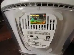
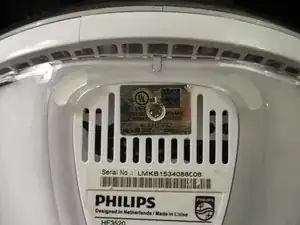
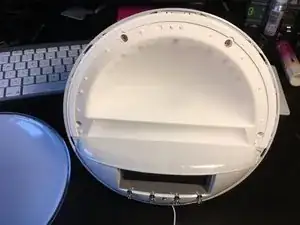
There is a screw under the shiny UL sticker. Remove the sticker or pierce it to unscrew and remove this bottom panel.
-
-
-
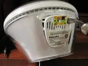
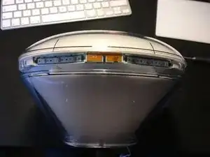
Flipping the light on its back will present a small section of the bezel that can be pried out. It is a small plastic strip with hooks that have to be disengaged to be removed.
-
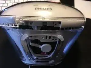
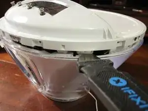
Push the blade of the jimmy directly into the crevice above the cover. Once it has gone a few millimeters, tilt it to lift the cover slightly.
-
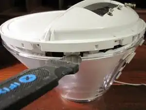
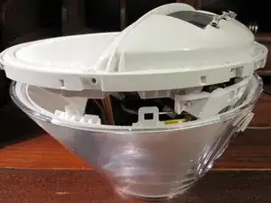
Slide the jimmy to the right side and press it against the latch to release it. Do the same for the left side.
-
-
-
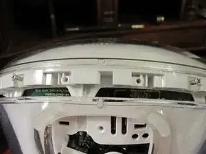
We can finally unscrew two more Philips head screws to remove the button ring.
-
Tip: Lift one end of the ring, tilting it toward the back of the alarm clock. That will get the hooks out from under the rear rim so you can start removing it..
-
-
-
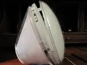
Now the six screws holding the front screen need to be removed and the screen can be pulled away to the front.
-
-
-
There are two tabs that hold the assembly in on the bottom left and right sides.
-
Using a jimmy — or any flexible, flat, metal tool, such as a putty knife — press the back tabs inwards to release.
-
-
-
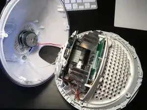
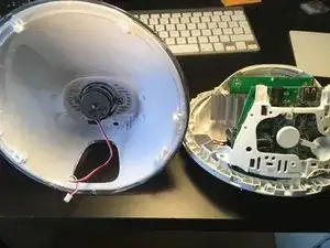
Disconnect the speaker from the main circuit board.
-
Loosen the screw and washer inside the back cover by the speaker and unwrap the antenna wire that was pinned underneath. Pull the antenna all the way through so the back cover can be removed.
-
-
-
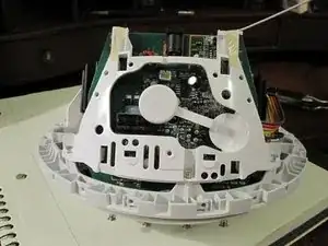
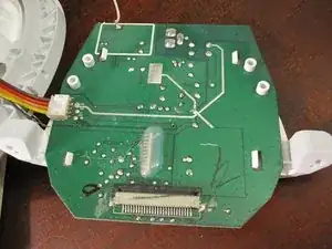
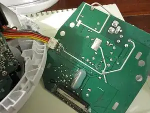
Remove the three screws at the base of the white plastic holder that is clipped into the main PCB. The circuit board will now lift slightly but be stopped by a ribbon cable.
-
-
-
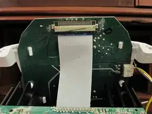
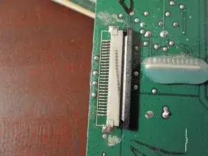
The ribbon cable can be released by pulling forward the tabs on the sides of the connector. Now the circuit board can swing to the side.
-


To reassemble your device, follow these instructions in reverse order.

There is one screw under this tab that's hold the front ring attached in fact. I guess you should have removed it too before prying this ring open
Luuk Akkerman -
That one does not hold the ring but the cover (step 4).
Wozu das denn -