Introduction

Follow this guide to replace the back button boards in your Sony DualSense Edge controller.

If your LB or RB button isn't working correctly, you may need to replace the back button board.

  1. x4vwaRsDyyrnGO1H
    x4vwaRsDyyrnGO1H
    GqAfoBfvBQYJpSEc
    HBjKPWcMs4BNEHWD
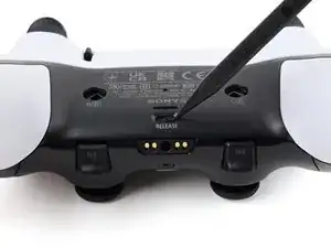
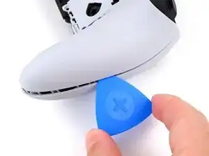
    • Place the controller on a work surface with the joysticks facing down.

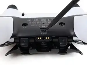
    • Use a spudger or your finger to slide the Release tab to the left. The front trim should fall to the table.

    • If the front trim doesn't fall open, make sure the front trim has room to fall down and the Release tab is pushed all the way to the left.

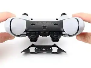
    • Lift the controller up, leaving the front trim on the table.

    • During reassembly, insert the front trim at an angle so the top slots in first, then lower the trim into place and snap it onto the controller.

  2. pUNR3yecJAZYLaKc
    pUNR3yecJAZYLaKc
    SdsSUTDZa5uS6EZS
    P5iZgQ6mPQOMRHmc
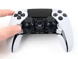
    • Flip the controller over so the joysticks are facing up.

    • Lift the metal lever that holds the joystick in place until the joystick slides out slightly.

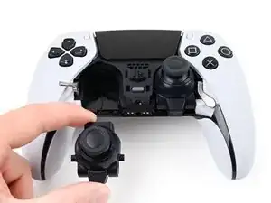
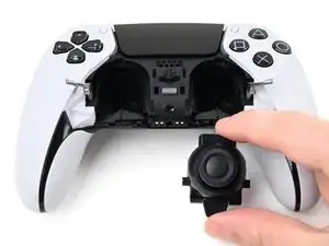
    • Slide the joystick out from its slot.

  3. Cf1NCMPonpThsBwU
    • Repeat this process to remove the other joystick.

  4. d1KAp3HdKaog3guy
    d1KAp3HdKaog3guy
    kENsDKyd5SKPM4rD
    myL4VPDY6joP3uMu
    • The rear trim is held in place by fragile plastic clips. Work slowly and gently to avoid breaking the clips.

    • If you installed the back button paddles included with your controller, remove them before beginning this process.

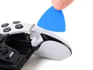
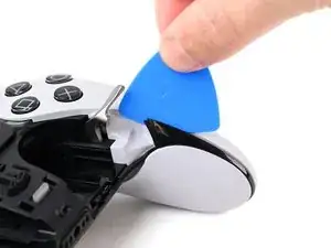
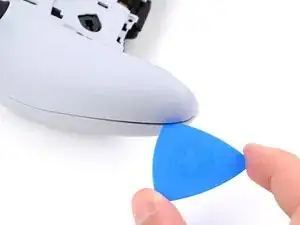
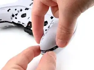
    • Insert the flat edge of an opening pick between the black portion of the rear trim and the top cover, near the joystick lever.

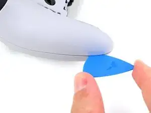
    • Slide the opening pick towards the bottom of the grip to release the clips.

  5. hM5LPbjjnNW1YKIb
    hM5LPbjjnNW1YKIb
    JWvVE61rY6bnxZAn
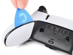
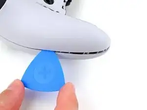
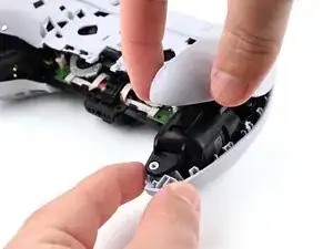
    • Slide the pick around to the rear of the controller and flip the controller over so the buttons are facing down.

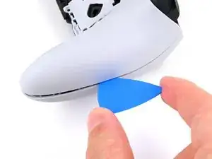
    • Slide the opening pick around the edge of the rear trim to release the clips.

  6. uZDemQgoDljXNVQd
    uZDemQgoDljXNVQd
    VxxmVV2UCMtKGm1E
    eyCuK1PuKWCXOitX
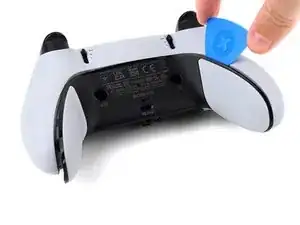
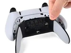
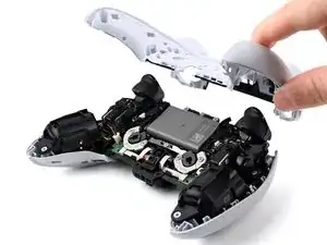
    • Slide the opening along the edge of the trim on the other grip.

    • Once all clips are released, remove the trim.

    • If at any point the trim feels stuck, stop and look for any clips that may have re-engaged and release them with the opening pick to avoid damaging them.

  7. evowF64RhL6gaqLK
    evowF64RhL6gaqLK
    heRVpgAiWYVhElng
    63HkRMysMPTSXLMU
    • The L1 and R1 buttons are held in by two clips. If only one clip releases, move your spudger to the other side of the button to release the remaining clip. Don't continue prying on one side after a clip is released, or you risk breaking the other clip.

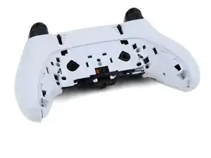
    • Insert the flat end of a spudger in the gap between the L1 and L2 buttons.

    • Use the spudger to pry out the L1 button.

    • The buttons tend to shoot out in this step. You can place your thumb over the button to prevent this.

    • Repeat this process to remove the R1 button.

  8. im1oEMoANZa3OPxx
    im1oEMoANZa3OPxx
    ODADaFvQYuFhYsOP
    • Remove the two 6.4 mm screws behind the L1 and R1 buttons.

    • Use a JIS J0 driver or an official iFixit Phillips PH0 driver, which is designed to be cross-compatible with JIS screws. Using a screwdriver other than an official iFixit driver or a JIS driver may result in stripped screws.

  9. SbCOjhiMBmbOmDmO
    SbCOjhiMBmbOmDmO
    PVUJqFqJwKi51nDE
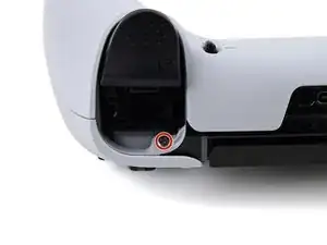
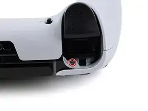
    • Rotate the controller so the grips are pointing towards you.

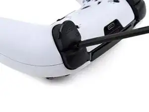
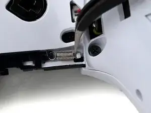
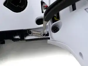
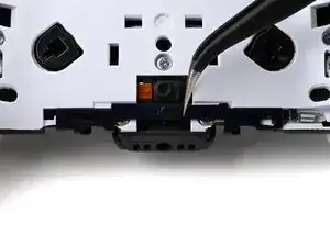
    • Use a pair of angled tweezers to lift the right end of the release bar spring off of the white post.

    • The spring is located below the RB button.

  10. yWg36HJBZIB2D6nY
    yWg36HJBZIB2D6nY
    CrQfqR2gLUksAAyL
    1qbbJIURBpD1ZBjP
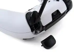
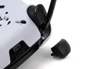
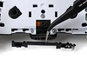
    • Use a pair of tweezers or your fingers to slide the release bar to the left.

    • Slide the release bar away from the controller to remove it.

  11. 6IhKTcgcHMQZPkWT
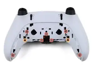
    • Remove the nine screws securing the rear case:

    • Seven 6.4 mm‑long screws

    • Two 10.5 mm‑long screws

  12. BIaokQhWthYBpYEA
    BIaokQhWthYBpYEA
    Syq5UswaP1ZrjN1b
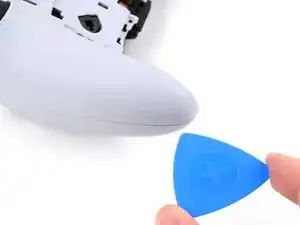
    • Insert the point an opening pick in the gap along the outside edge of one of the controller grips, near the bottom.

  13. oNEIKTmy1J5cRQJp
    oNEIKTmy1J5cRQJp
    PANUUX4PLjFi5uf3
    B6CeLYMEG2FNakDB
    • Pry with the opening pick to separate the rear case from the front case by releasing the clips that hold them together.

    • Continue prying along the edge of the controller until one side is separated.

  14. 4jKadtLlPcC6uOd1
    4jKadtLlPcC6uOd1
    2uiq6pMXeCljGExA
    • Repeat this process to separate the other side of the rear case.

  15. mUNIaZPZTMesONej
    mUNIaZPZTMesONej
    mtJMa3FRILpNLMlK
    cONdiGShuN14EcSd
    • If at any point the case feels stuck, stop and look for any clips that may have re-engaged and release them with the opening pick to avoid damaging them.

    • Hold the main body of the controller with one hand.

    • Lift the rear case with your other hand. It should lift at an angle.

    • Pushing slightly towards the L and R buttons, lift the rear case off of the controller and remove it.

    • During reassembly, make sure the plastic covers for the adaptive trigger assembly adjustment sliders are correctly installed over the sliders.

  16. Pm3lfcqRDuWJaKCq
    Pm3lfcqRDuWJaKCq
    RkhqbJFmUYwnFUM4
    EBFqn4fAGgblKMN5
    • The rear case holds two small plastic covers for the adaptive trigger assembly adjustment sliders. These may have come off during removal. Place them back in the rear cover now to avoid losing them.

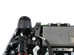
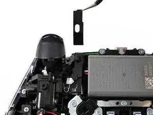
    • Use a pair of tweezers or your fingers to lift the cover from the controller.

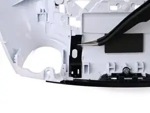
    • Slide the flat end of the cover under the plastic tab in the rear case.

    • Make sure it is placed so it can move freely in its groove. The edge with the notch should be towards the middle of the controller.

    • If a cover got bent during the rear case removal or reassembly process, apply a small amount of heat with a hair dryer to restore it to its original shape.

    • During reassembly, you can use a small piece of painter's tape on the outside of the rear case to hold the covers in place.

  17. PkDh5CkScncXEXuF
    PkDh5CkScncXEXuF
    65eostWqjLfxV5ul
    • If your battery is swollen or deformed in any way, take appropriate precautions.

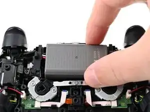
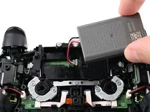
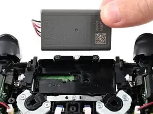
    • Lift the battery and move it to the right, so the connector underneath the battery is accessible.

  18. fLdPAxr2bkkwmh3R
    fLdPAxr2bkkwmh3R
    CXAwhwBLYJwS3X24
    QA2dDoXwiKEKIMYH
    • Use the flat end of a spudger to pry up the low profile connector.

    • Only pry on the connector. Do not pry on the wires, as that may damage the wires.

    • Remove the battery.

  19. EksvuEBXEkW2ku6k
    • These instructions are for the RB back button, which is to your left. The instructions are identical for the LB back button.

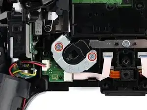
    • While holding the back button switch down, remove the two 6.4 mm‑long screws securing the back button bracket.

  20. RjlYMqfMRyI5wDkW
    RjlYMqfMRyI5wDkW
    tnSfIQTwPJSQGO4K
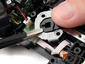
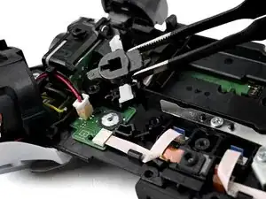
    • While holding the back button switch down, use a pair of tweezers or your fingers to lift and remove the back button bracket.

  21. BfNOjLupOsiwZcZb
    BfNOjLupOsiwZcZb
    fbX1fEQIWCWiDLU6
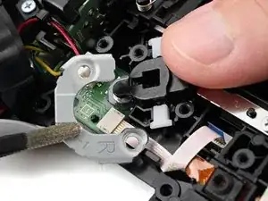
    • Use a pair of tweezers or your fingers to lift and remove the back button switch, being careful not to lose the plastic covers on the sides of the switch.

    • During reassembly, make sure the white plastic covers are in place, seated fully, and oriented correctly.

  22. 22CjNVWBHRfvZeJI
    22CjNVWBHRfvZeJI
    jsiKpxYj5PYxWbTi
    • These instructions are for the RB back button board, which is to your left. The instructions are identical for the LB back button board.

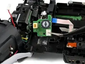
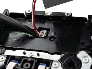
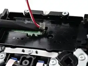
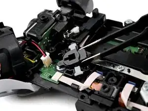
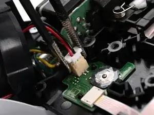
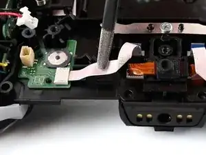
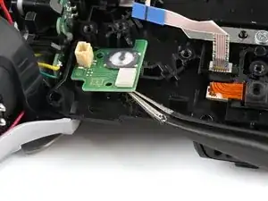
    • Use a pair of tweezers to disconnect the vibration motor cable from the back button board by lifting the JST connector out of its socket.

    • Only pull on the connector. Pulling on the wires may break them.

  23. QSFCKEjuMQDZfkoG
    QSFCKEjuMQDZfkoG
    g3QwASO6MCMMP1Iy
    • Use a pair of tweezers to move the back button ribbon cable out from its plastic clip.

  24. djTNxPVDiHUG3OVw
    djTNxPVDiHUG3OVw
    GIgvDh6SmjGcInq5
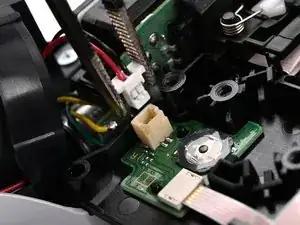
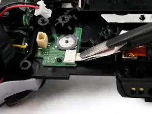
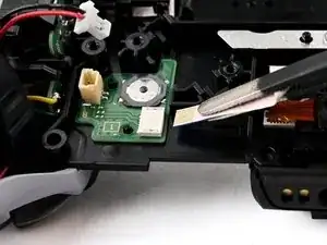
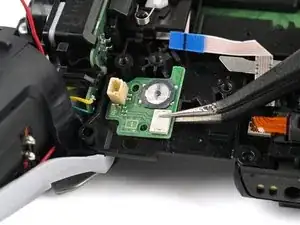
    • Use a pair of tweezers to disconnect the back button board ribbon cable by gripping the blue tab and pulling away from the back button board.

  25. GKkRe5RHvxH5xDPS
    GKkRe5RHvxH5xDPS
    PFBcJFTXq2aHfeFX
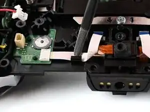
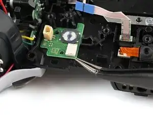
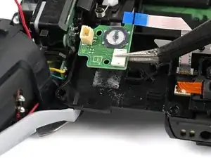
    • Insert a pair of angled tweezers under the bottom inside corner of the back button board.

    • Use the tweezers to pry up the back button board until it comes free of the adhesive underneath it.

  26. YniluSyPDUHObxdF
    YniluSyPDUHObxdF
    VYBM5agwo2nZOfUN
    • Use a pair of tweezers or your fingers to lift and remove the back button board.

Conclusion

To reassemble your device, follow these instructions in reverse order.

Take your e-waste to an R2 or e-Stewards certified recycler.

Repair didn’t go as planned? Try some basic troubleshooting, or ask our Answers community for help.

Spencer Pennington

Member since: 09/09/23

17064 Reputation

5 comments

where i can buy this back button board ?

Seba -

yeah where are these PCB boards?

Bobby Austin (Fun-Bobby) -

I cant find them either… where to buy

Adam Schafer -

I also need this board. The little button stopped popping back up.

Trynafixit -

In my device the plastic parts under the metal carrier broke. It has a sort of lever action that I'm pretty sure was intended to break.

It would be no good to reassemble it with baking soda and super glue. Aside from buying a scrap controller there doesn't appear to be a way to return it to original.

Any help appreciated.

Luther St. Ama -