Introduction

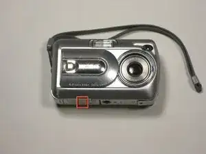
This guide explains how to replace the flash unit of a FujiFilm FinePix A340 camera.

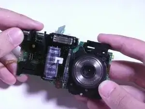
The flash unit is a mechanism within a camera that creates a "flash" or quick burst of light while a photo is taken to illuminate the image. If the "flash" function of your camera is not working, you may need to replace your flash unit.

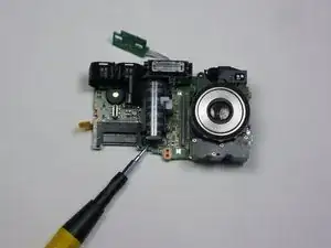
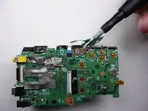
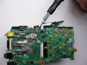
Note that this guide involves soldering, or using a special tool called a soldering iron to delicately weld parts together.

  1. Pkt3FmqJAJ4aQLDB
    • To prevent the danger of electric shock, remove the batteries before continuing to the next steps.

    • Slide the battery cover to the side to release the batteries.

  2. vmRqxIHXMXfnccM1
    vmRqxIHXMXfnccM1
    Fgu3NMD2PrESRQSM
    6yWExUFP3GMeI43j
    • Remove the five screws from the camera casing using a tri-point Y0 screwdriver.

  3. fAhbFy25dmJLRN2h
    fAhbFy25dmJLRN2h
    wFY3hhf6RXgwDrsl
    • Grab the case with your hands and slowly pull back the outer casing.

  4. 4ajevGoBgvNcgrMu
    • Locate the LCD screen and anchoring screw.

    • Remove screw.

  5. eQXTqDBGiQWjfHOq
    • Carefully pull the LCD screen away from the board it is connected to.

  6. HwIDHLHKLbqNmSMZ
    • Push both blue switches away from the holding device to detach the LCD ribbon.

    • Be careful when removing the ribbon. If you damage it, you will need to replace it as well.

  7. bMLVTGfgqxoHSQnS
    • Carefully detach the ribbon from where it was connected by the blue pins.

  8. E1BaJJrZ3cESyaiM
    • Now that everything has been disconnected from the board, remove LCD screen.

  9. TBJLP4wWVapldHRS
    • Remove the two screws holding the circuit board down.

  10. xOlWPjj1wryHrk53
    xOlWPjj1wryHrk53
    AiUE5c5F5eGvCGuo
    • Remove the black sticky tape from the circuit board and camera case.

  11. UHUaTvOGPLURWbIY
    UHUaTvOGPLURWbIY
    ZnXU4N4YDBxMCABZ
    • Gently pull the circuit board away from the front side of the camera.

    • Be careful when removing the assembly as to not break any solder leads or damage the lens assembly.

  12. gsOUCxgnKxyFIrus
    gsOUCxgnKxyFIrus
    qMu2OPBj3SLCeYS4
    • Remove the motherboard by pulling it straight away from the assembly.

  13. MEDGaydQDWMTCyMB
    • Locate the flash unit of the camera. It includes the camera's flash and a capacitor.

  14. KCEAIWkAEF5golGB
    KCEAIWkAEF5golGB
    MEXLq4xqVAUrBATG
    • Desolder the flash unit at its three points.

    • Be careful not to damage the circuit board or surrounding parts with the solder iron.

    • Learn more about electronics soldering here.

Conclusion

To reassemble your device, follow these instructions in reverse order.

Cody

Member since: 19/04/10

47 Reputation

0 comments