Introduction

A device's motherboard is the center of its operations. Any problems with it will cause the device to malfunction. Depending on the severity of the damage to the motherboard, replacement may be necessary, and this guide will show you how to do that.

  1. YcNyyQ55kjFDWIin
    YcNyyQ55kjFDWIin
    jbVGJWPartJPsRct
    5DKd6HdeLMBPMJZH
    • Unscrew the six 3.5mm Philips head from the outer casing.

  2. FO53dLrrIoaTKbEd
    FO53dLrrIoaTKbEd
    kPWFcIUZLtsVRpbZ
    I1kHUJSXdSapxAqd
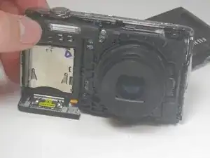
    • Open the battery compartment and remove the battery.

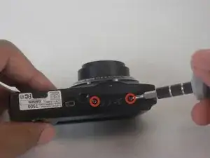
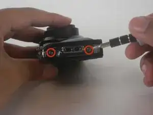
    • Carefully pry the front half of the casing away from the camera.

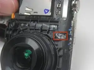
    • Pay close attention to the sensor cover—a small piece of translucent plastic—as it may fall out of place. If it does, place it back in its original position.

  3. rGJaLMMvByKQgIUY
    rGJaLMMvByKQgIUY
    U2AS5IiRPJZi4eXV
    • Pry the back half of the casing from the camera.

    • Be careful when maneuvering the camera without the casing on as the LCD screen is not fastened to anything.

  4. O1ZWINJVLpRFM6DK
    O1ZWINJVLpRFM6DK
    UFCvPJiIM12Lwliu
    yrUSxSDAKaKJfJQF
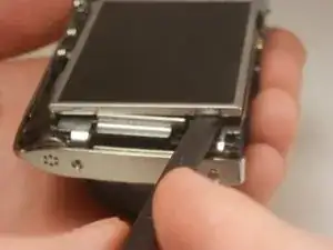
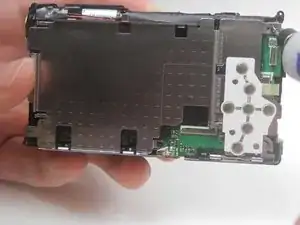
    • Lift the LCD screen out of the camera.

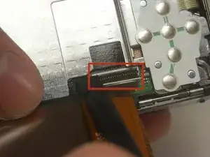
    • Locate the tab securing the ribbon cable that connects the screen to the motherboard. Using a spudger, gently lift the tab to release the ribbon. Carefully disconnect the screen from the motherboard.

  5. FBoPTSqmxBrHQ3BA
    • Unscrew the 3.5 mm Phillips head screw from the corner of the camera.

  6. 4OZYuQpEnOEj2kQy
    4OZYuQpEnOEj2kQy
    XyUd5fop3ZwKP2D5
    mSCaaBRSGyTXBhpG
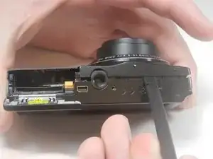
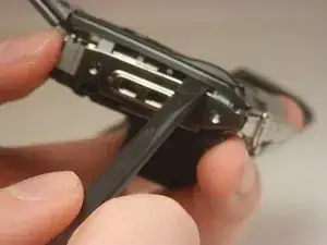
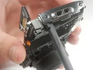
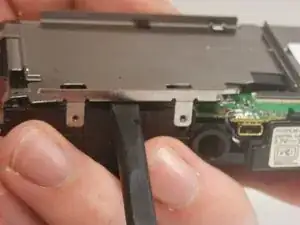
    • Pry off the center casing of the camera. Separate the top and side sections individually before fully removing the casing.

  7. iWLuaA4TeX25pumP
    iWLuaA4TeX25pumP
    RJaFxWVHdyDyHPaL
    LZtDCmgJEplfek3V
    • Unscrew the two 3.5 mm Phillips head screws in the metal plate.

  8. ph6StbMNMGKgqRRr
    ph6StbMNMGKgqRRr
    wbMvlIF2BGiLgpkt
    • Pry the metal plate out using the spudger.

  9. aZsTrFfq3pELkTc2
    aZsTrFfq3pELkTc2
    2mUCBFoJsUF1Hlbf
    T4rgIHuwWRFUQNfP
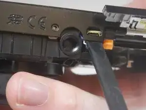
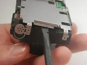
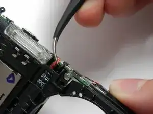
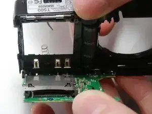
    • Peel back the strip of black tape to reveal a red and black wire.

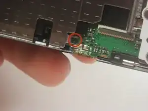
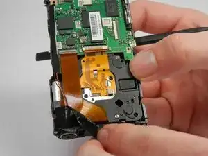
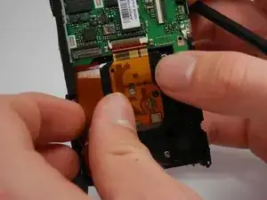
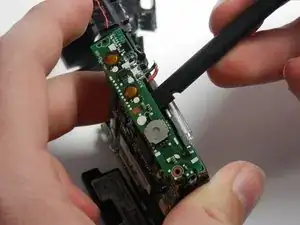
    • Detach the orange ribbon by gently pulling on it.

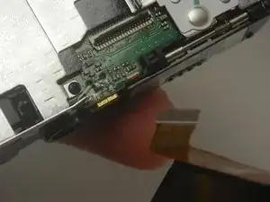
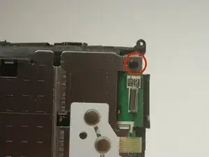
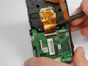
    • Detach the golden ribbon by gently lifting it with the spudger.

  10. yHku1ODnbhZKmA2b
    yHku1ODnbhZKmA2b
    jFEvoxEZIpWXbtIb
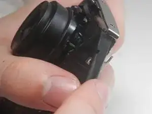
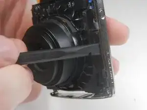
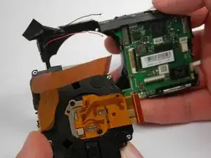
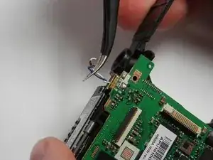
    • The lens should now be free to simply be pushed out of its socket.

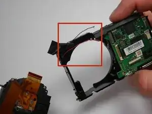
    • The black and red wires that were exposed previously may be in the way of removing the lens and may break. If they do, you will need to solder these wires back into place upon reassembly.

  11. nOYyeCadyFxCFyNb
    • Use tweezers to pull back the plastic covering the top of the camera.

  12. KPjEDHZ3xHS2gBBQ
    KPjEDHZ3xHS2gBBQ
    VXEKxQZGfrMgbwXt
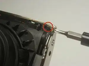
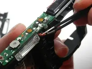
    • Use tweezers to disconnect both the red and the black wires located next to the flash of the camera.

    • These wires will need to be soldered back in place upon reassembly.

  13. 6OoUs5RVmbq4nF6a
    • Pry off the top circuit board using the spudger.

  14. IjKkoC1LiQrUBQqy
    • Use tweezers to disconnect the blue and white wires on the underside of the camera.

    • These wires will need to be soldered back in place upon reassembly.

  15. 2UVO2ZDScNtRyXVm
    • Push the motherboard out of the camera body.

Conclusion

To reassemble your device, follow these instructions in reverse order.

Brian Lasher

Member since: 16/01/15

325 Reputation

0 comments