Introduction
The GamStop Universal System is a device that allows you to connect multiple systems to your television, while easily switching between the systems. The mother board contains majority of the important technology in order to allow multiply gaming platforms to run simultaneously. Therefor this guid requires more time and has a higher difficulty. This guid also requires tools such as a screwdriver, pliers, soldering iron as well as a lead free solder in order to properly complete the replacement of the mother board.
-
-
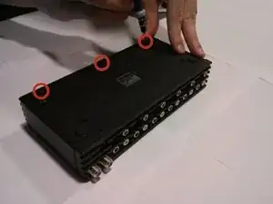
Pop off the front two rubber footings from the bottom of the device, revealing 2 hidden main panel screws.
-
-
-
Position the device so that its bottom is on your work surface, and its top is facing up.
-
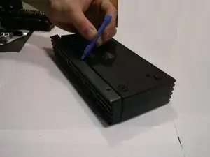
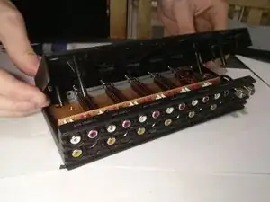
Slowly remove the lid by placing both hand on the shorter sides of the device and lift from only one side.
-
-
-
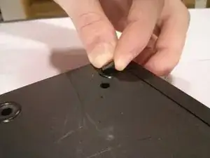
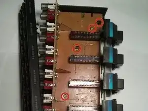
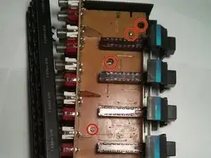
Remove all six screws from the circuit board.
-
These screws look similar to others already removed, therefor ensure they are placed in a secured area.
-
-
-
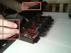
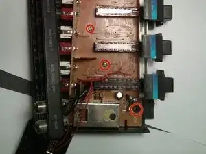
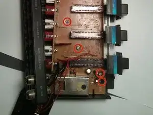
Now the circuit board should be able to be removed from the casing of the device except for two wires that are attached to the casing.
-
Detach the black wires from the casing, by carefully pulling them out of the cable ports.
-
Using pliers or a similar tool, detach the red wires from the small circuit board that is attached to the case of the device.
-
-
-
Now it's time to replace the old circuit board with the new one.
-
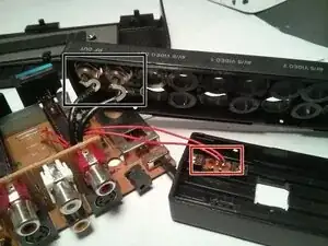
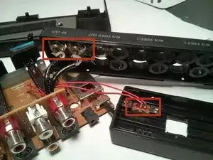
Push the two black wire's ends into the cable ports on the back panel of the casing.
-
Solder the ends of the two red wires onto the small circuit board on the front panel of the device.
-
-
-
Correctly place the circuit board back into the case of the device and replace all six screws on the circuit board with the screwdriver.
-
-
-
Using the same method when detaching the panles, carefully lower it back down onto the mother board
-
Snap the front and back panels back into place and screw the corresponding screws into their original place on the back of the device.
-


The device should now be working properly. If the device does not function properly the replacement motherboard may be faulty, or the wires may not have been properly connected.