
Introduction
Follow this guide to replace the rectifier diodes on a Genesis GHG1500A Dual Temperature Heat Gun.
If you find that the heat gun is not working and your multimeter indicates a shorted diode, then this guide should help.
I recommend replacing all 4 diodes so that all of the diodes have the same specs. This should reduce the likelihood of compatibilty issues in the future.
-
-
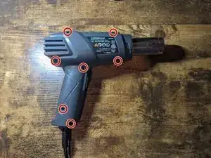
Remove the seven 14mm screws from the side of the drill using a phillips screwdriver.
-
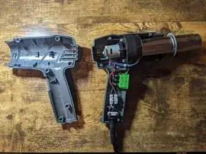
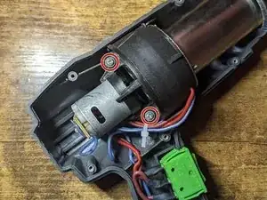
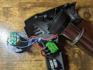
Remove the top casing to reveal inside of drill.
-
-
-
Using a phillips screwdriver remove the two 12.5 mm screws that are holding the fan housing to the bottom case.
-
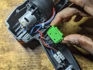
Lift switch out of the bottom case.
-
Lift wires out of their retaining slots.
-
-
-
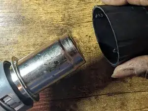
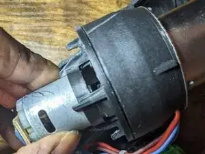
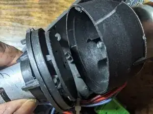
Seperate the fan unit from the plastic housing that is attached to the metal shield.
-
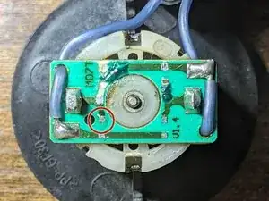
Position fan and metal shield so that you can comfortably work on the circuit board located on the top of the motor.
-
-
-
-
Quickly move the soldering iron back and forth between both ends of the diode while adding fresh solder until the diode is released from the pads.
-
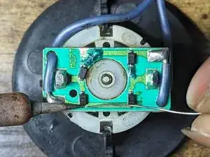
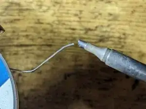
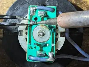
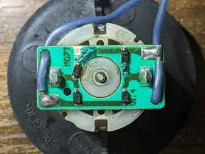
Method 2 (2 soldering irons) [Photo 2]
-
Heat up both soldering irons.
-
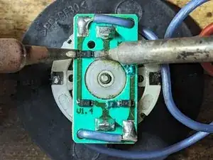
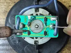
Add fresh solder to both ends of the diode. (Photo 1)
-
Hold soldering irons on both ends of the diode and lift the diode off of the circuit board once the solder melts. (Photo 2)
-
Repeat the above steps for the remaining diodes.
-
-
-
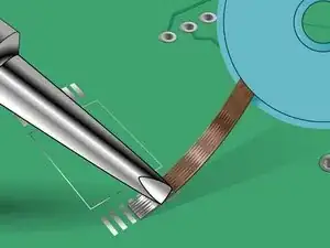
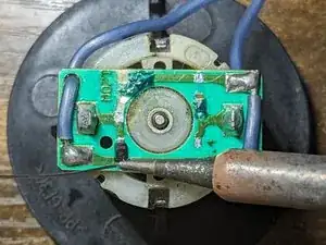
Remove excess solder from pads. (Link to desoldering video and the importance of flux)
-
Add flux to the pads
-
Apply flux to desoldering wick braid
-
Place desoldering wick braid on top of the pad
-
Press the iron on the braid until the solder on the board wicks into the braid.
-
Repeat above steps for the remaining pads.
-
-
-
Add flux to pad. (Photo 1)
-
Add small amount of solder to the tip of the iron. (Photo 2)
-
Use tweezers to hold the diode centered in between both pads. (Photo 3)
-
Touch the iron to the pad to tack the diode into position
-
-
-
Add flux to second pad. (Photo 1)
-
Hold iron onto the second end of the diode and feed solder onto the board right at the tip of the soldering iron. (Photo 2)
-
Revisit the first end of the diode and repeat the step above to ensure a sufficient amount of flux is on the pad. (Photo 3)
-
Use isopropyl alcohol on a q-tip to clean any excess flux left on the board.
-


To reassemble your device, follow these instructions in reverse order.