Introduction

Use this guide to replace the display panel in your HP 15-fc0000 series laptop.

Note: This procedure was written using a model 15-fc0093dx HP 15 Laptop PC but is compatible with any HP 15 Laptop PC whose model number starts with 15-fc.

This procedure requires removing the battery to disconnect it. Use care to avoid bending, twisting, or puncturing it—a charged lithium-ion battery can be very dangerous if accidentally punctured. If your battery looks puffy or swollen, take extra precautions.

  1. yTLHBPRpQqW2ShcC
    • Shut down the laptop.

    • Unplug the charger and any other cables from the laptop.

  2. UnMHxtysYjMmTCZN
    • Close the laptop and flip it over so the rubber feet are facing up. Place the laptop on a soft surface to avoid damaging the top cover.

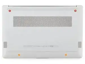
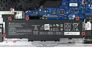
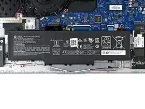
    • Use a Phillips screwdriver to remove the four screws securing the bottom cover.

    • Two 6.8 mm‑long screws near the rear of the laptop.

    • Two 4.8 mm‑long screws near the front of the laptop.

  3. OLx62NwqcG2BtuwZ
    OLx62NwqcG2BtuwZ
    jTPC4oZTyHViSBmN
    • The clips attached to the bottom cover are fragile. Use caution when releasing them.

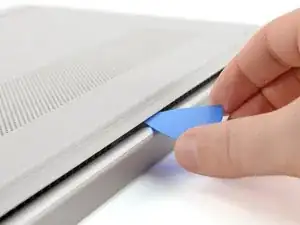
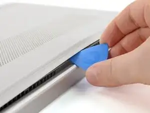
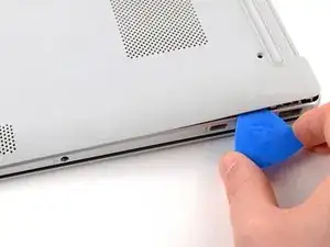
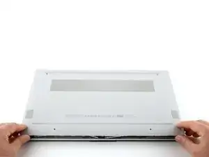
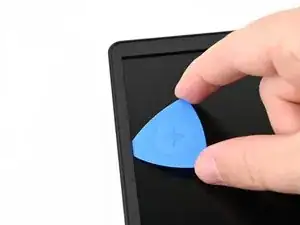
    • Insert an opening pick under the bottom cover at the rear of the laptop.

    • Twist the pick until one or more clips release.

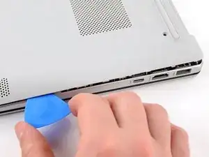
    • Repeat this procedure along the rear edge until you release all the clips.

  4. wguY4oSAl1ii6Eaj
    wguY4oSAl1ii6Eaj
    Y1SJrH1qdKoaRtJy
    • The bottom cover is fragile. Use caution when bending it.

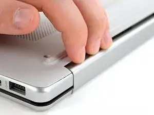
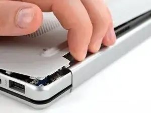
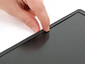
    • Place your fingers under the part of the bottom cover you've raised, near a corner.

    • Use your fingers to gently pry up the corner of the bottom cover.

  5. KjWqRMSf5XC3iyYF
    KjWqRMSf5XC3iyYF
    d46wGsWgGxqWC3rP
    rHDaCZyIgfLW3SPY
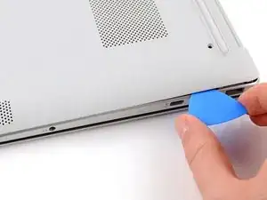
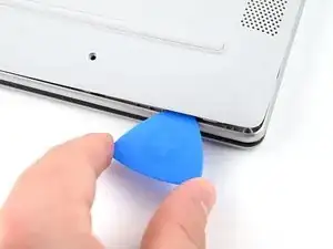
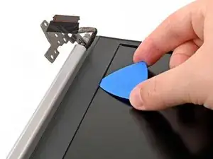
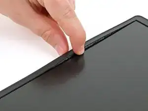
    • Insert an opening pick under the edge of the bottom cover next to the corner you've raised.

    • Pry up the back cover clips along the edge.

  6. g42hLGpPvQZfexvq
    g42hLGpPvQZfexvq
    KuwCUsUmHpLlqUVu
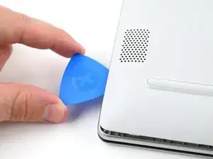
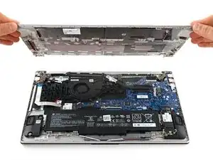
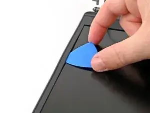
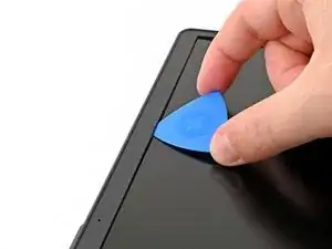
    • Use an opening pick to repeat the procedure from the previous step to pry up the remaining sides of the bottom cover.

  7. DBVIiCdyftmaZKOw
    DBVIiCdyftmaZKOw
    QpLYSYRlZiHUsDpA
    • Remove the bottom cover.

    • Some clips may re-engage when you're releasing other sides. If the bottom cover doesn't lift off easily, use the opening pick to release any remaining clips.

    • During reassembly, lay the bottom cover on the laptop so the sides of the cover align with the sides of the laptop. Then, gently press on the sides until you hear the clips click. If the clips don't engage easily, adjust the cover and try again.

  8. dhQgkHgWMcOJBxMt
    dhQgkHgWMcOJBxMt
    YiYWyeYFCFGL3e3s
    • Do not put too much stress on the wire, as that can harm your laptop's audio quality.

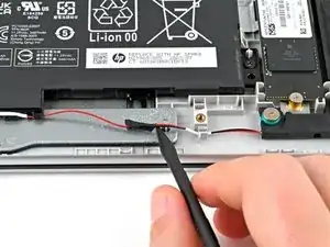
    • Use a spudger or your fingers to lift the tape that adheres the speaker wires to the metal trackpad bracket.

    • Try not to fold the tape so it can be reused during reassembly.

  9. LuFkJWDhDwWvCG4E
    LuFkJWDhDwWvCG4E
    hUKIXwpQEfbuTOsn
    AEEYs5p5DOGLrYqF
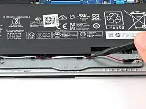
    • Use a spudger or your fingers to remove the speaker wires from the routing clips along the edge of the battery.

  10. NbDESHH53pXZLNeZ
    NbDESHH53pXZLNeZ
    BfiSfPrIrYMa3aiy
    • Use a Phillips screwdriver to remove the five 4.3 mm‑long screws securing the battery.

    • During reassembly, press firmly on the battery connector to ensure a strong connection.

  11. SmqQMOUQZAi5vgTO
    SmqQMOUQZAi5vgTO
    MUU2KCROlMcUxNQF
    VkDC6dH3ReXspjbB
    • Do not grab the battery at the ends because this battery is flexible. Instead, grab the battery one inch from each end to better support the middle.

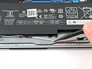
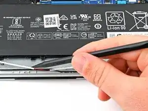
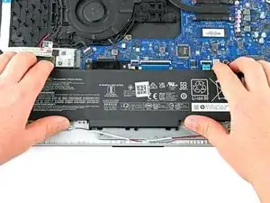
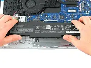
    • Use two hands to grip the battery about one inch from each end.

    • Lift the front of the battery (the side closest to you) until the battery is free of its alignment pegs.

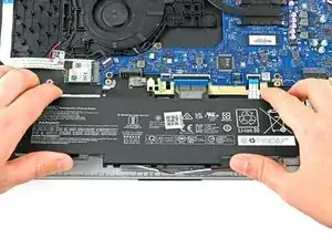
    • Pull the battery towards you to release it from its connector.

    • Don't continue to use a damaged battery, as doing so is a potential safety hazard. If in doubt, replace it with a new battery.

    • During reassembly, insert the battery onto its connector at a slight downward angle before pressing it flat to the frame.

  12. nFAlCM5MCaoXEOWM
    nFAlCM5MCaoXEOWM
    WKSBMRi1QJTnKKjA
    • The right hinge is on the left side since the laptop is upside down

    • Use a Phillips screwdriver to remove the three 5.6 mm‑long screws securing the right hinge.

  13. KHoqZkTvwNyEeKDO
    KHoqZkTvwNyEeKDO
    rXEc6ig6NQrhhfPu
    • Lift the left hinge to 90º so it's pointing upward.

  14. 5sYjiDchy11AgiMv
    5sYjiDchy11AgiMv
    CNLCOnnhfhH3Y5Lg
    • The left hinge is on the right side since the laptop is upside down

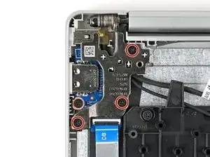
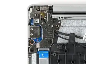
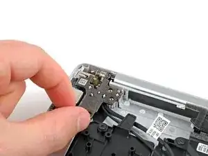
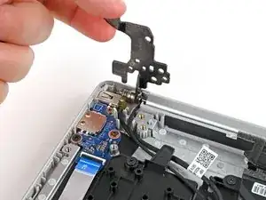
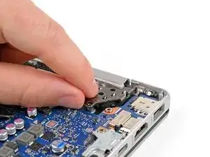
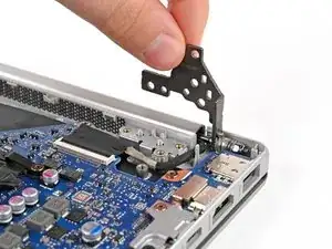
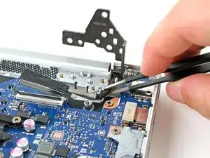
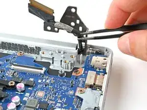
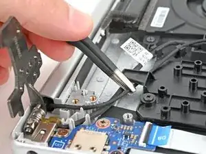
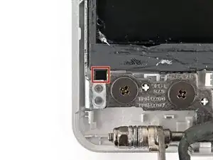
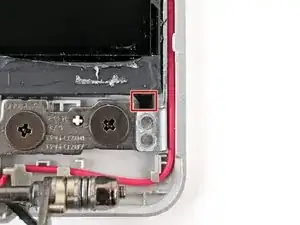
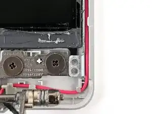
    • Use a Phillips screwdriver to remove the three 5.6 mm‑long screws that securing the left hinge.

  15. PXcPXvqUIOpjyjD6
    PXcPXvqUIOpjyjD6
    V3NRnjFLRHotpU4T
    • Lift the left hinge to 90º so it's pointing upward.

  16. dmECRBWjtDaofLPh
    dmECRBWjtDaofLPh
    niLM4RnwQnCRTeF2
    • Use the flat end of a spudger to pry up the locking tab on the display cable ZIF connector.

  17. PRGMWeqUgCKeDegy
    PRGMWeqUgCKeDegy
    VNjwyVoHrTIK6efL
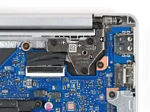
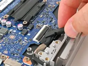
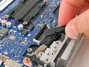
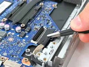
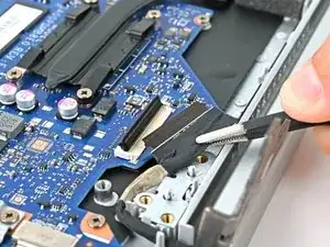
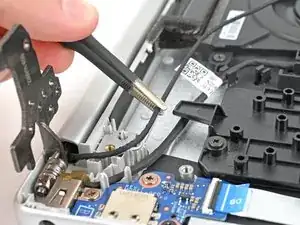
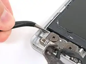
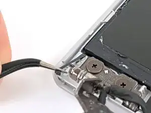
    • Use tweezers or your fingers to grip the black taped portion of the display cable.

    • Pull the ribbon cable away from its connector to disconnect it.

    • When reconnecting this cable, make sure the locking tab is fully open (up). The cable should slide in with minimal force. If you feel resistance, check that the locking tab is fully open and the cable is aligned, then try again.

  18. CHOHmAlndBKMflFR
    CHOHmAlndBKMflFR
    ZEST6rXXGBSrrKqI
    • Use tweezers to lift the display cable up and out of its routing channel.

  19. UoHIPo3iKSrIpCvG
    UoHIPo3iKSrIpCvG
    B46vSNHUAAOLudxs
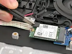
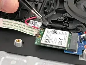
    • Use tweezers to remove the plastic cover on the wireless LAN card antenna cable.

    • Set the plastic cover aside with the sticky side up.

    • Keep the adhesive on the back of the plastic cover clean, as you will reuse this during reassembly.

  20. MfIMRWAEjdoNsNRG
    MfIMRWAEjdoNsNRG
    GryiHcNorXibDZxI
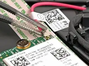
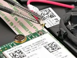
    • Place one arm of a pair of tweezers under the metal head of the antenna cable. Lightly grip the head.

    • The pictured laptop only has one antenna cable, but yours may have two.

    • Lift straight up to disconnect the antenna.

    • It's important to lift the connector straight up. If lifted at an angle, you risk breaking the socket off of the board underneath.

    • During reassembly, use tweezers to hold the connector in place over its socket and gently press down with your finger or a spudger—the connector should "snap" into place. If you're having trouble, reposition the head and try again.

  21. aZWV1QlnVh4fsiiG
    aZWV1QlnVh4fsiiG
    fledmscO1bJ6EcxS
    Q3tyaAUXDavrTFA3
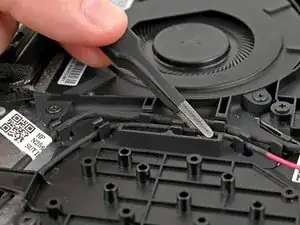
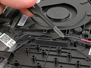
    • Use tweezers, a spudger, or fingers to lift the wireless LAN antenna out of the routing clips beside the fan.

  22. N2pU12cKUITQI6dh
    N2pU12cKUITQI6dh
    odYlEJZY2JeBSwxJ
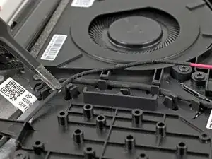
    • Use a pair of tweezers to move the wireless LAN antenna from underneath the plastic arm that holds it down.

    • If your DC‑in cable is on top of your wireless LAN antenna cable, gently pull it out from underneath the DC-in cable before proceeding.

  23. jJfZS21hhjRCkRrG
    jJfZS21hhjRCkRrG
    SED6iSX4lOmXgFxk
    oX1Q1dL4HVOgFsXe
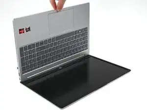
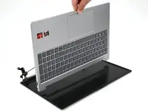
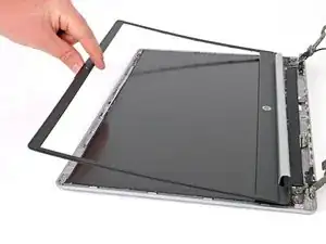
    • Lift the frame of the laptop so it is at 90º to the display assembly.

    • Slide the frame towards the webcam until it's free from the hinges.

    • Make sure the display cable and wireless LAN antenna are out of the way from the frame.

    • Now you're left with the display assembly for replacement.

  24. JYOMyGPeVxchkaLg
    JYOMyGPeVxchkaLg
    YufCglklgFWm61PC
    • The bezel is thin and can be broken easily. Work slowly, and don't lift the bezel at sharp angles.

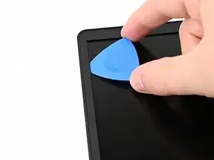
    • Insert an opening pick on the inside of one of the thinner sides of the display bezel, between the bezel and the display panel.

    • Cut the adhesive by sliding the opening pick along the display bezel.

    • The pick should slide easily. If it's difficult, you may be separating the conductive tape on the display panel. Take your pick out and re-insert it in a different location, trying to insert it at as low of an angle as possible.

  25. tROf6qtDOYsc5r4X
    tROf6qtDOYsc5r4X
    GV2uZa5GAACZRl1r
    PWRfZ32aZbTOwbO4
    • Slide the opening pick along the perimeter of the bezel until all of the adhesive is cut.

    • The bottom of the display bezel (the side with the HP logo) is wider. The entire width is secured with adhesive, so you'll need to insert the opening pick further.

  26. sdymsGCkaUW3CdCK
    sdymsGCkaUW3CdCK
    uGW6YfI4uuKkOKVI
    • Release the clips holding the display bezel by gently lifting the bezel, starting with one of the thinner sides.

    • The bezel is thin. To avoid breaking it, if it is difficult to remove, use the opening pick to slice any adhesive that may have become reattached.

  27. bI4tWJMsoVyx1V5T
    bI4tWJMsoVyx1V5T
    Ch1CSgMxvhLJCnKR
    • Lift the bezel and slide it out from underneath the hinges to remove it.

    • The bezel can be replaced without applying new adhesive. However, if your new bezel includes new adhesive, use isopropyl alcohol (>90%) and a lint-free cloth to remove any adhesive residue from the display panel.

    • You may also apply new adhesive, such as Tesa tape, to create a better seal.

  28. YrqjrfQJIamSPZHw
    YrqjrfQJIamSPZHw
    OocIMNMTONCer12y
    aKNxIBSCdUgacQc6
    • The display panel is secured with stretch-release adhesive, which may break if you pull too quickly, or at too high of an angle. Follow these instructions closely and take your time to avoid breaking the adhesive.

    • Use a pair of pointed tweezers to grip the pull tab below the lower-left corner of the screen and pull it up slightly so it's above the display assembly.

    • Slowly pull the adhesive straight back at a low angle until all of the adhesive is separated.

  29. mrI1cNRMB6cEaDkF
    mrI1cNRMB6cEaDkF
    cwGTMRID6s4QVm1j
    • Locate the pull tab of the stretch‑release adhesive below the lower‑right corner of the display panel, then repeat the procedure from the previous step to remove this adhesive.

  30. 5MSkkLXPmQuIYmDE
    5MSkkLXPmQuIYmDE
    4SIHH4AhISIebW5I
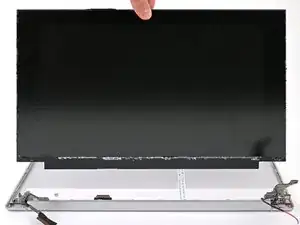
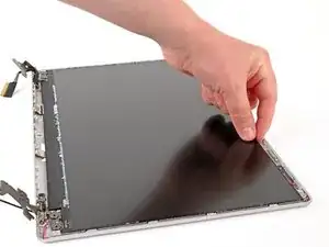
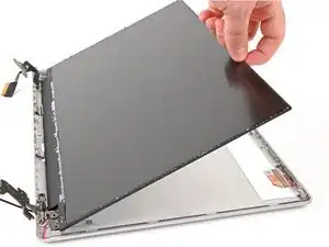
    • Lift the display panel from the top of the panel (the side closest to the webcam).

    • Hold the panel at 90º or prop it against something sturdy for the next step.

  31. wdBfePiH6tTQjAyi
    wdBfePiH6tTQjAyi
    Ip1JBLoD2GiscIky
    evsDTwX61IajqRYJ
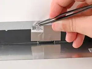
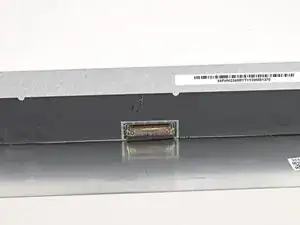
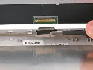
    • While the display panel panel is being held or propped up at 90º, use a pair of tweezers to remove the fabric tape covering the display cable connector on the back of the display panel.

    • Keep this tape clean so it can be reused during reassembly.

  32. OpoHvdetbWmjUmZa
    OpoHvdetbWmjUmZa
    UqQPaey3NJuLlSUs
    • Use the flat end of a spudger to lift the locking buckle over the display connector.

  33. JTpRJ3HINS6IHaBK
    JTpRJ3HINS6IHaBK
    DKIYYJxcWmteaIGs
    UPJkB25Uw5if5yrH
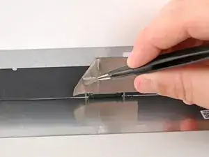
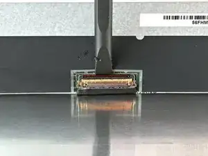
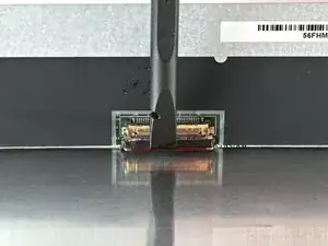
    • Use a pair of tweezers to grip the display cable and the buckle.

    • Holding the display cable in place, lift the display panel to disconnect it from the display cable.

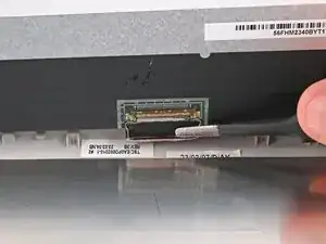
    • Remove the display panel.

Conclusion

To reassemble your device, follow these instructions in reverse order.

Take your e-waste to an R2 or e-Stewards certified recycler. Depending on your region, used HP devices and parts can be returned for reuse or recycling through the HP Planet Partners program.

Repair didn’t go as planned? Try some basic troubleshooting, or ask our Answers community for help.

Spencer Pennington

Member since: 09/09/23

17064 Reputation

0 comments