Introduction
This guide will demonstrate the replacement of the motherboard of an HP EliteBook 840 Aero G8. This replacement may be necessary as a last resort fix for a computer, as individual parts will usually break before a motherboard does. The main reasons to replace the motherboard will most likely be poor general performance or physical damage to the board.
The tools necessary will be a Phillips Head #0 (PH0) screwdriver, a Phillips Head #1 (PH1) screwdriver, an iFixit opening tool, a spudger, and tweezers.
It is important to note the prerequisite guide, the HP EliteBook 840 Aero G8 Speakers Replacement Guide. The speaker system must be removed to begin this replacement.
-
-
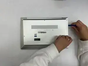
Turn the laptop upside-down.
-
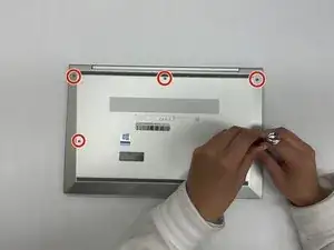
Remove all five of the 4.48mm housing screws using a Philips #0 screwdriver.
-
Remove the cover using an iFixit opening tool.
-
-
-
Using the iFixit opening tool, remove the right-hand side speaker.
-
Using the iFixit opening tool, remove the left-hand side speaker.
-
-
-
Using the plastic spudger, disconnect the speaker power cable.
-
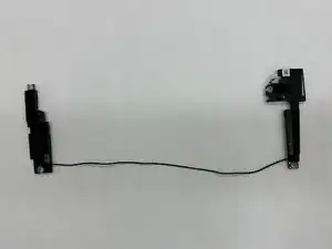
Remove the wire from the device apparatus until it is fully isolated. The speaker system can now be removed from the computer to fix or replace as needed.
-
-
-
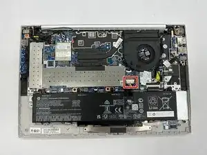
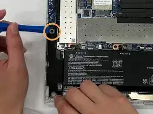
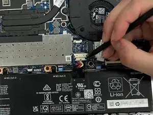
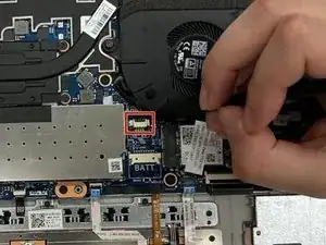
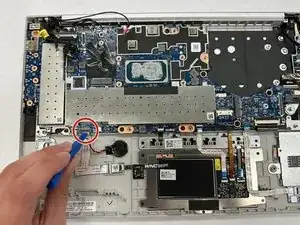
Using the spudger, unplug the battery from the motherboard.
-
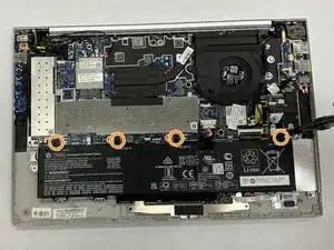
Use the PH1 screwdriver to remove the screws from the battery.
-
Remove the battery from the casing.
-
-
-
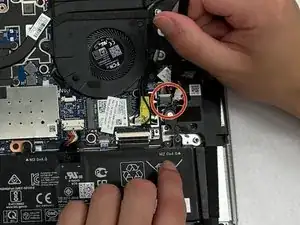
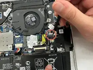
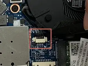
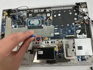
Using the spudger, unplug the fan power cable from the motherboard.
-
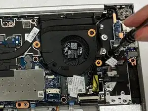
Use the PH1 screwdriver to remove the three 4.48 mm screws.
-
Remove the fan from the computer.
-
-
-
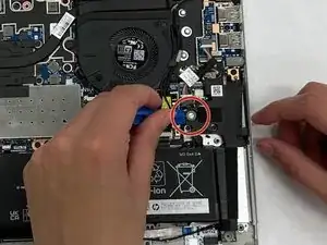
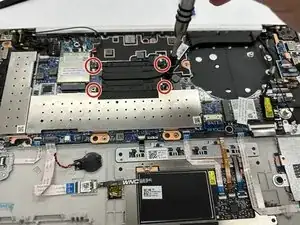
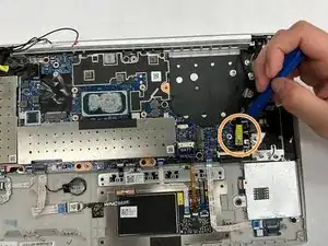
Use the PH1 screwdriver to unscrew the heat sink from the motherboard.
-
Remove the heat sink from the computer.
-
-
-
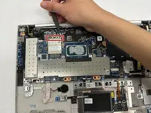
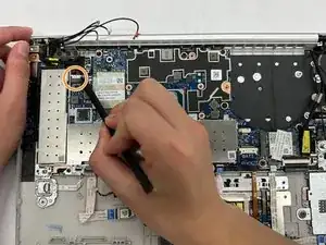
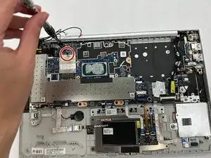
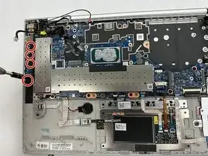
Use a PH1 screwdriver to remove the 4.48 mm screw that secures the WAN card on the left side of the motherboard.
-
Use a PH1 screwdriver to remove the 4.48 mm screw that secures the WLAN card located on the right side of the motherboard.
-
-
-
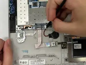
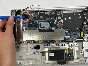
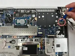
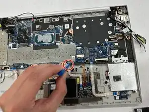
Using the iFixit opening tool, disconnect the camera power cable on the left hand side of the motherboard.
-
Using the iFixit opening tool, disconnect the camera connection cable from the right-hand side of the motherboard.
-
-
-
Using a PH1 screwdriver, remove the bracket holding the left side of the motherboard in place. These four screws are the longer of the two types of screws found in this laptop, measuring 4.48mm in length.
-
-
-
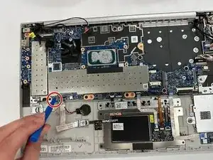
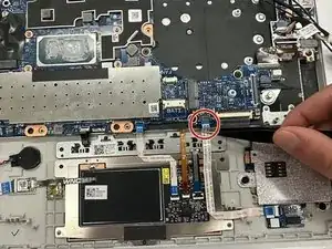
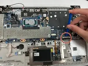
Using tweezers, gently pull on the smart card reader board to disconnect it from the motherboard.
-
-
-
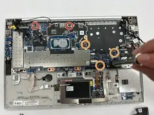
Use the PH1 screwdriver to remove the two 4.48mm screws from the motherboard.
-
Use the PH1 screwdriver to remove the three 2.52mm screws from the motherboard.
-
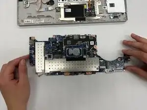
You can now remove the motherboard from the computer to replace or fix it, as needed.
-
To reassemble your device, follow these instructions in reverse order.