Introduction

This guide will instruct you on how to safely remove and replace the motherboard in your HP Elitebook x360 830 G6. Removing your motherboard is a significant repair to your laptop and requires careful maneuvering of all parts included to ensure nothing gets broken. Keep in mind that the connections between certain parts and the motherboard are fragile. Excessive force to remove, or replace, any part should not be needed. If you find yourself straining to remove, or replace, a part, please review the steps to ensure you are doing it correctly. Proper storage of every part and screw is extremely important when completing this guide. When taking any hardware off of the motherboard, place it somewhere safe as you will need to install it onto your new motherboard.

  1. fESHQOj5PtAqJsDQ
    • For your safety, discharge the battery below 25% and power down your device before disassembly.

    • Use a Torx T5 screwdriver to loosen the five captive screws holding the back cover.

  2. RTxWGUAUnnPXAVfs
    RTxWGUAUnnPXAVfs
    cSjfRl1nKBuUoiid
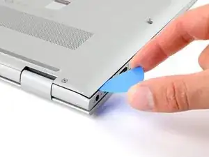
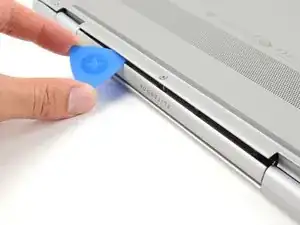
    • Insert an opening pick between a corner of the back corner and the chassis, near a hinge.

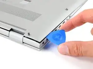
    • Pry upward to release the retaining clips.

    • These clips will make an audible click when they release.

    • Repeat this process for the opposite corner.

  3. HGtvRsSvrYsFZ4LJ
    HGtvRsSvrYsFZ4LJ
    WOefBICHEOheGTUg
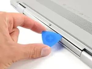
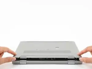
    • Insert your opening pick between the back cover and chassis, along the edge of the cover between the hinges.

    • Pry up to release the additional retaining clips.

  4. bGRoZIZ3K2YqEtGo
    bGRoZIZ3K2YqEtGo
    IJnDNINPggsQCWXC
    DVkPBsu1GvLslCmR
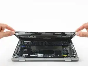
    • Grab the cover by the corners next to the hinges.

    • Swing the cover open and away from you.

    • If the back cover feels stuck to the chassis, use an opening pick to release remaining clips around the perimeter of the back cover.

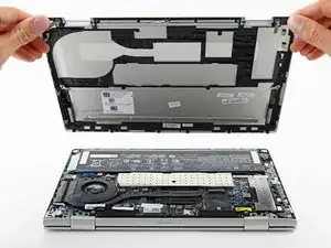
    • Lift and remove the back cover from the laptop body.

  5. tKyLMuFyeBJyOweE
    tKyLMuFyeBJyOweE
    svQOMvweDN1YWvoU
    3wAjSXvojBPNNQAF
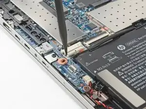
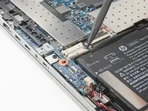
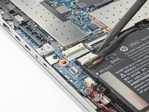
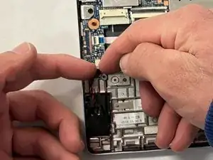
    • Use the point of a spudger to push the sides of the battery connector out of its socket.

    • Push on alternate sides to "walk" the connector out.

  6. YDw3eCTokvL5mopR
    • Use your Phillips screwdriver to remove the five 4.2 mm-long screws securing the battery.

  7. Fe4xxiyLGTvJIMaI
    Fe4xxiyLGTvJIMaI
    cin4HuwGFtseJPEl
    4k4RvYXIRC1evQNp
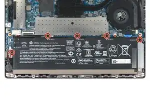
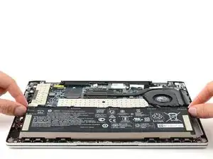
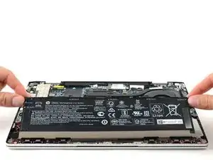
    • Pull the battery out from the retaining tabs at the front of the chassis.
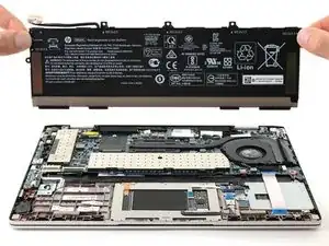
    • Remove the battery.

  8. KIKWJCFp323Gh2mD
    KIKWJCFp323Gh2mD
    ngCW2onWox5vSCiK
    JwiUspq243vIRcg5
    • With your spudger, pry up on the tabs at the top and bottom of the SSD cover.

    • This will loosen the SSD cover enough for it to pop out from its tension clips.

  9. nPok4n1eak5RpyNJ
    nPok4n1eak5RpyNJ
    rfUSAnxdCLB6MsUM
    • Lift the SSD cover off the SSD and remove it.

  10. kPQBXvDXRlKCF3Ry
    kPQBXvDXRlKCF3Ry
    CP2WUpQ6cpxvbp6c
    • Use your Phillips screwdriver to remove the 2.4 mm-long screw from the SSD.

  11. uVGiqsCMFcSXMEvX
    uVGiqsCMFcSXMEvX
    2jaxDJBwxhtRlnRx
    rcANDwPYNSUhvvvR
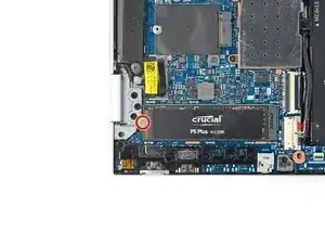
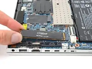
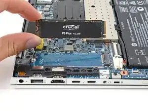
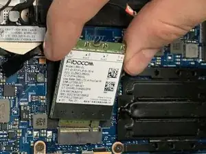
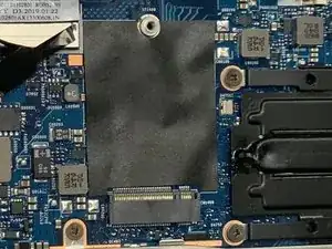
    • Grip the edges if the SSD near the screw indent.

    • Pull the SSD straight out of its socket and remove it.

    • If the SSD feels stuck, wiggle it side to side as you pull.

  12. ZarQYCSIsG6nsIHY
    ZarQYCSIsG6nsIHY
    Fg5sdMDxhahFk3Dw
    DbvPg1Nblfftpxh1
    • Use your fingers or the pointed end of a spudger disconnect the CMOS battery connector.

  13. M5lbpSYvtAPIWOoH
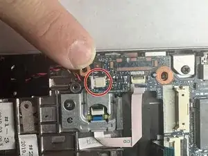
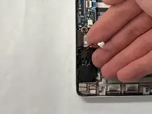
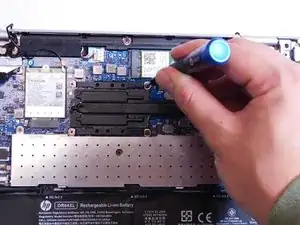
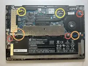
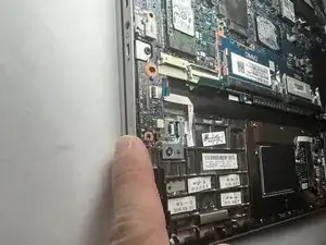
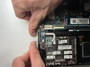
    • Remove the CMOS battery from its housing by pulling up the small, black plastic tab that is holding it in place.

  14. XCoKSteGwBojdKuu
    XCoKSteGwBojdKuu
    ZtJ3lNqOCwBMnTYA
    vXVRAm1y3Y5YfwQO
    • Using the Phillips #0 screwdriver, remove the seven 3 mm screws from the cooling system.

  15. 6Ok3nJGKlkvZvbM4
    6Ok3nJGKlkvZvbM4
    PNYXjCrlcaf1agA5
    A3dwGKvVKYswWZ6j
    • Remove the three 3mm captive screws from the fan using the Philips 0 screwdriver.

    • Using needle nose tweezers, gently grab the base of the connection and pull to disconnect.

  16. 2Ad5DaYlfWCuLjNr
    • Separate the fan and cooling system from the motherboard.

  17. FkmXrLMIMnBVuVsu
    FkmXrLMIMnBVuVsu
    ffs1OLOaQE3DSeea
    • Remove the two antenna cable with tweezers.

    • The blue tagged antenna will be on the left side. The red tagged antenna will be on the right side.

  18. KxVgfUf3GenRQoZ1
    KxVgfUf3GenRQoZ1
    pB36jTRRLuDGNF1S
    • Use a Phillips #0 screwdriver to remove the 3 mm screw securing the Wi-Fi card.

    • The card will pop up at a slight angle once the screw is removed.

  19. HpYF5IpEXjWUEfYR
    HpYF5IpEXjWUEfYR
    vNmjrAQYkRBTlDIj
    • Grasp the sides of the Wi-Fi card to slide it out of the socket to remove.

    • Gently remove the Wi-Fi card. There is risk of damage to the socket if removed forcefully.

  20. 5krBuBjOts2b2eZ4
    5krBuBjOts2b2eZ4
    wQMriuHPJ4EUlYSx
    w3aLLmmDTpjaGiyA
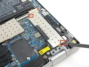
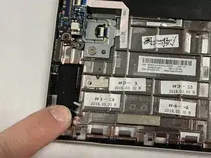
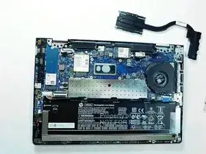
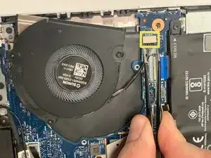
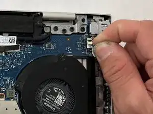
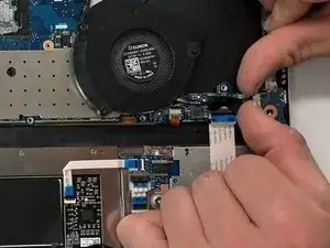
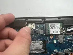
    • Remove each no-fuss ribbon connector by gently pulling the blue tab straight away from the port with your fingers.

    • To disconnect the ZIF connectors, use the tip of your fingernail to flip up the small locking flap. Then disconnect the ribbon cables.

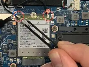
    • Grab the black plastic loop of each of the connectors pull it upwards away from the motherboard.

    • When pulling out the ribbon, do not pull up and away from the laptop. Doing so may damage the ribbon or socket.

  21. 5pHCkRDvjnDdcmpF
    5pHCkRDvjnDdcmpF
    Zf4YLAKcnVOPTFHO
    chhfP1Rsp4ka1GVx
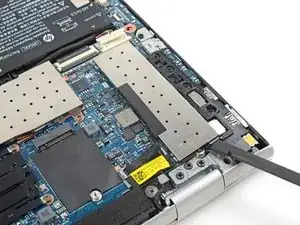
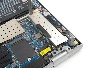
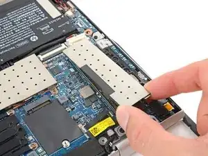
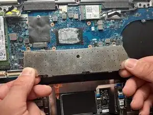
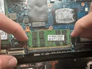
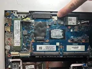
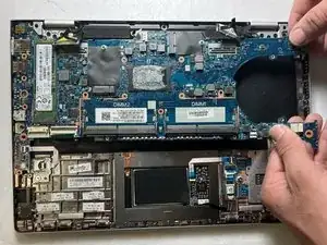
    • Remove the metal shield that covers the RAM module.

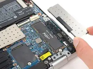
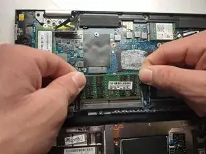
    • Gently pull the two silver retaining arms apart until the module flips up a few millimeters.

    • Remove the RAM module.

    • Pull the memory card straight back out of its slot to avoid damage to either part.

  22. IDLMR2hNgUX3qt3o
    IDLMR2hNgUX3qt3o
    V5VoJMbIBUVLsjS1
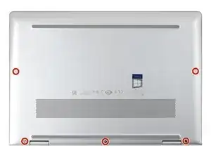
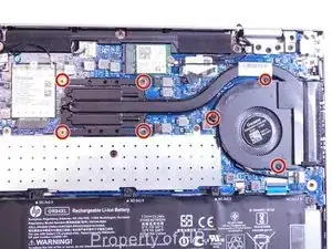
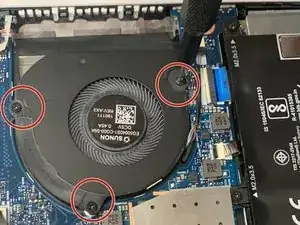
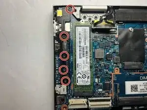
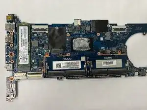
    • Use a Phillips #0 screwdriver to remove the five 4.1 mm screws from the plastic bracket.
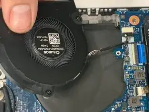
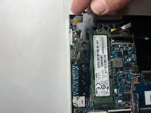
    • Remove the bracket.

  23. Wuu4VVWdaEe3wWq4
    Wuu4VVWdaEe3wWq4
    FjJk4rmTki5Ls22t
    • Push in then remove the SD card slot from the side of the laptop.

  24. Ikn1TolpWOJLVQsd
    Ikn1TolpWOJLVQsd
    Kx16TJLeXWVDWnVE
    • Remove the remaining cords connecting to the motherboard near the top.

  25. r21gYBBGxmNsPsVT
    r21gYBBGxmNsPsVT
    41m2gEhTj51QbfY3
    • Gently lift and remove the motherboard.

    • Do not tug or forcefully pull the motherboard to remove it. If there is any significant resistance, double check that all previous steps were completed and all accessories are removed.

Conclusion

To reassemble your device, follow these instructions in reverse order.

Brody Reder

Member since: 02/04/24

301 Reputation

0 comments