Introduction
This guide will show you how to replace the motherboard in your HP Elitebook x360 830 G7 laptop.
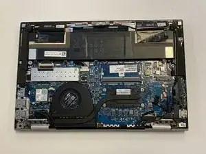
The motherboard is the 'mother' of all the components in your computer. It connects and controls all of the components and systems in the computer. Without a properly functioning motherboard, it is impossible for your computer to work as intended.
The motherboard will need to be replaced if it is damaged, but you may also want to replace the motherboard if you are replacing the CPU in your computer.
Before you begin this repair, turn off your laptop and unplug it from the charger.
-
-
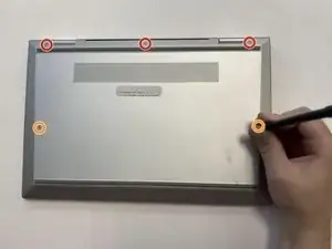
Turn the computer over so that the back is facing up.
-
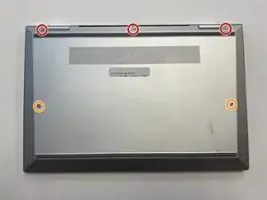
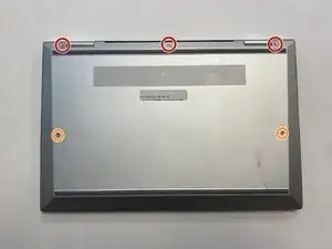
Use a Torx T5 screwdriver to remove the three 9 mm screws from the hinge of the device.
-
Use a Torx T5 screwdriver to remove the two 7 mm screws from the left and right mid-section of the case.
-
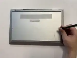
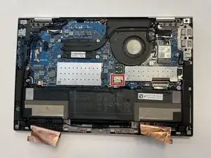
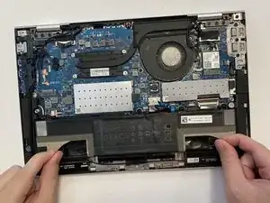
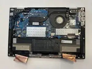
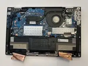
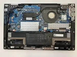
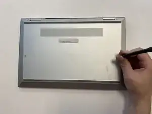
Lift the backplate from the computer.
-
-
-
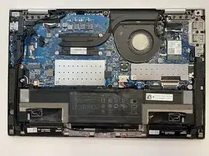
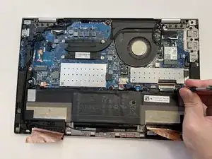
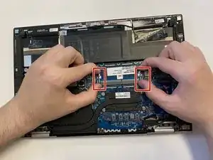
Use a nylon spudger to gently disconnect the battery's bundled cable connector from the motherboard.
-
-
-
Turn the computer over so the back is facing up.
-
Use a Torx T5 screwdriver to remove the three 9 mm screws from the hinge of the device.
-
Use a Torx T5 screwdriver to remove the two 7 mm screws from the left and right mid-section of the case.
-
Lift the backplate from the computer.
-
-
-
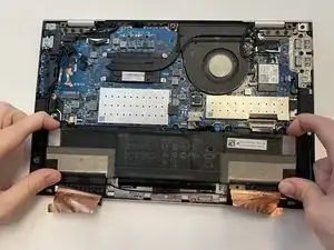
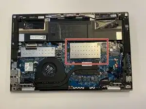
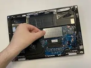
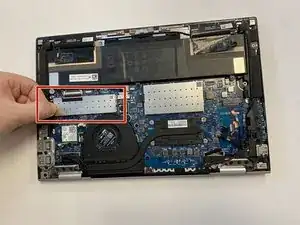
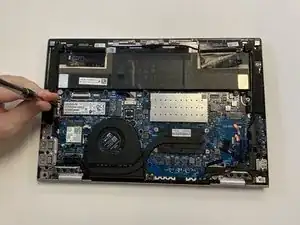
Push down on the two latches on both sides of the RAM to release it.
-
This will allow you to remove the RAM and replace it with no issues.
-
-
-
Turn the computer over so the back is facing up.
-
Use a Torx T5 screwdriver to remove the three 9 mm screws from the hinge of the device.
-
Use a Torx T5 screwdriver to remove the two 7 mm screws from the left and right mid-section of the case.
-
Lift the backplate from the computer.
-
-
-
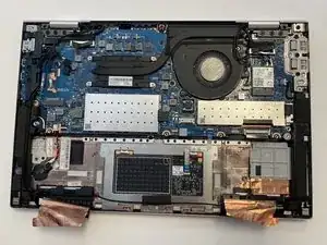
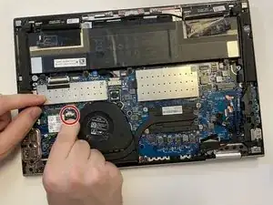
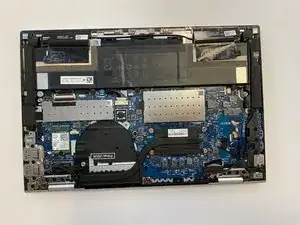
Remove the display panel and the wireless antenna cables from the routing channels. Then, remove the retention tape from the system fan.
-
-
-
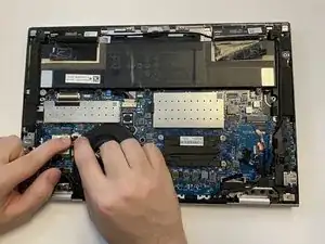
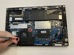
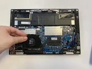
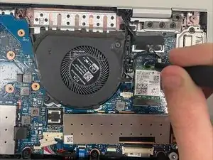
Once all of the connectors and screws that secure the fan in place have been removed sucessfully, you can safely remove the system fan from the motherboard.
-
-
-
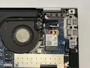
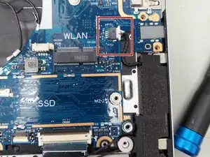
Use a JIS #1 screwdriver to remove the single screw securing the Wi-Fi card.
-
Use a spudger or or angled tweezers under the metal neck of the connector two connectors (as close to the head as possible) and lift straight up from the board to disconnect the coaxial cables.
-
Slide the Wi-Fi card out of the socket.
-
-
-
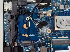
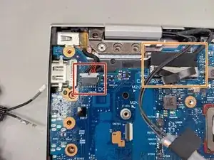
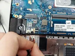
Disconnect four cables.
-
Use a JIS #1 screwdriver to remove the single screw.
-
Remove the WWAN module.
-
-
-
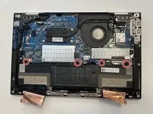
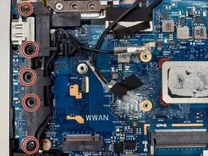
Use a JIS #1 screwdrivers to remove five screws securing the plastic bracket.
-
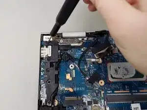
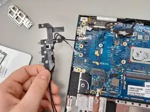
Remove plastic bracket.
-
-
-
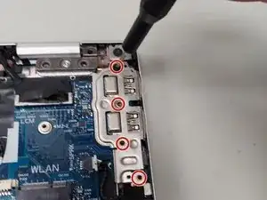
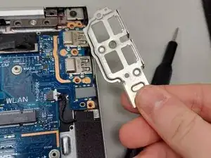
Use the JIS #1 screwdriver to remove four screws securing the metal bracket.
-
Remove metal bracket.
-
-
-
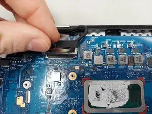
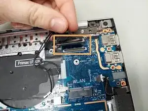
Use a prying tool to push on alternating sides of the power connector to "walk" it out of its socket and disconnect.
-
Pull straight up on the connector to disconnect camera cable.
-
-
-
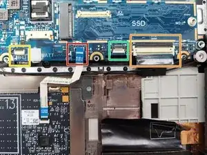
Use the point of a spudger to push on alternating sides of the speaker connector to "walk" it out of its socket.
-
Gently push the tip of a spudger under the metal buckle to unclip it, then swing it over the socket.
-
Hold the buckle and cable together and gently pull the connector straight out of its socket.
-
-
-
Disconnect touchpad cable. Lift up the small black lock and pull out the ribbon cable.
-
Lift up the small black lock and and pull out the ribbon cable to disconnect keyboard cable.
-
Disconnect keyboard ZIF connector backlight cable (if applicable).
-
Disconnect the ZIF card reader cable (if applicable).
-
-
-
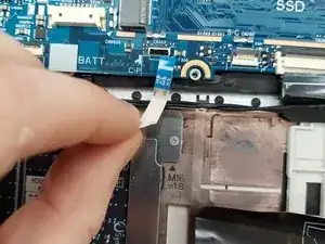
Use the point of a spudger to push on alternating sides of the RTC battery connector to "walk" it out of its socket and disconnect the RTC battery cable.
-
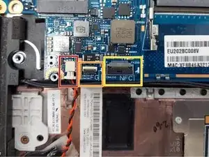
Disconnect NFC module ZIF connector to remove the cable (if applicable).
-
Disconnect Fingerprint reader ZIF connector to remove cable (if applicable).
-
-
-
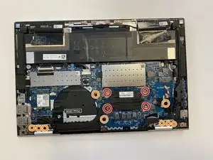
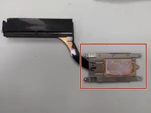
Use a Phillips #0 screwdriver to loosen the screws securing the heat sink.
-
Use a JIS #1 screwdriver to remove the remaining screws holding motherboard in place.
-
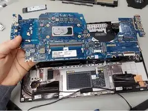
Lift the left side of the motherboard upwards and pull it out of the laptop.
-


To reassemble your device, follow these instructions in reverse order. Take your e-waste to an R2 or e-Stewards certified recycler.