Introduction
These instructions detail how to take apart an HP dv5000 laptop computer, how to identify and remove the fan from the computer, and how to reassemble the computer.
-
-
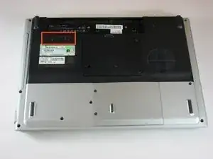
Lay the computer face-down on a flat surface. Orient the computer to match the image.
-
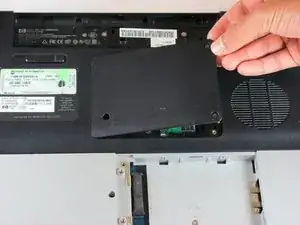
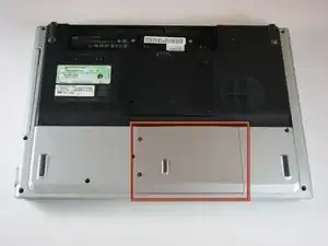
Locate the battery release switch, as indicated in the image by the red rectangle. Slide the switch from right to left, and remove the battery.
-
-
-
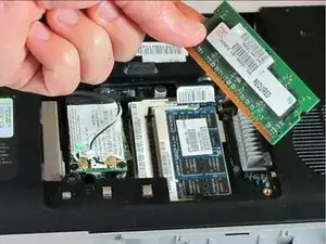
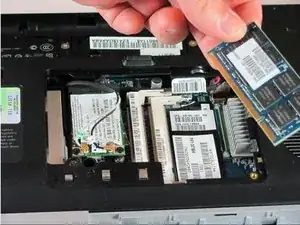
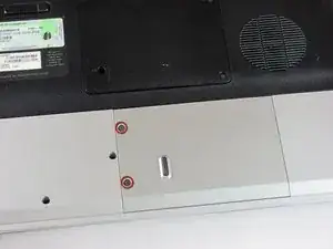
Remove the two 5mm Phillips screws on the right side of the RAM cover.
-
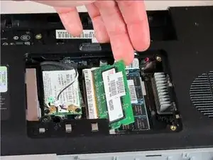
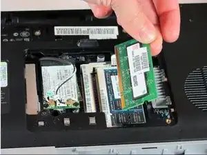
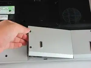
Lift the right side of the RAM cover, and remove it.
-
-
-
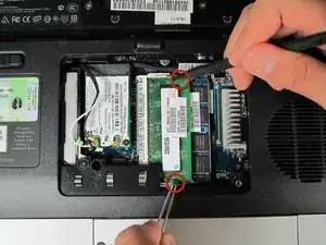
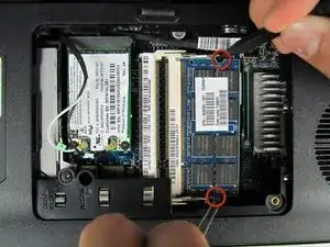
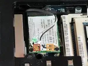
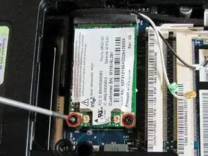
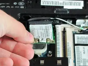
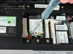
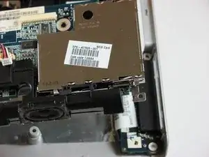
Disconnect the antenna leads from the wifi card by lifting the gold ends of the wires off the prongs on the wifi card.
-
The white wire connects to the AUX terminal.
-
The black wire connects to the MAIN terminal.
-
-
-
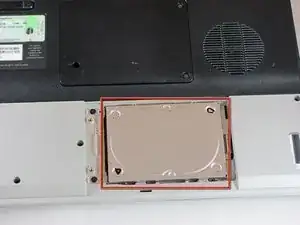
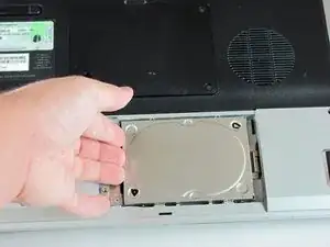
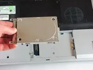
Slide the hard drive to the right until the edge of the hard drive is flush with the computer frame.
-
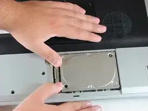
Lift the hard drive out of the hard drive bay, left side first.
-
-
-
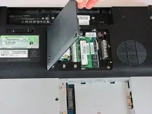
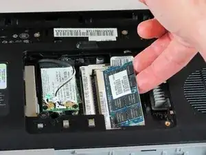
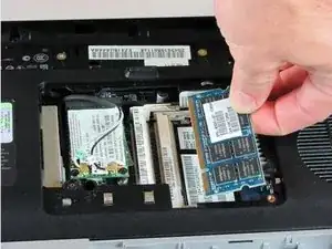
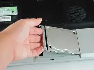
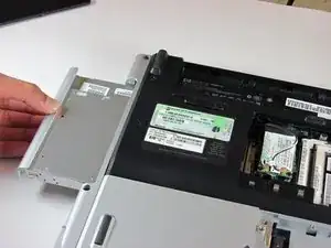
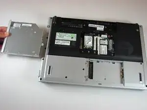
Locate the optical drive. The optical drive is located on the left side of the RAM bay.
-
Press the exposed edge of the optical drive gently with the spudger until the drive releases from the computer frame.
-
Pull the optical drive completely out of the computer frame.
-
-
-
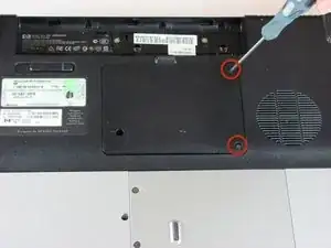
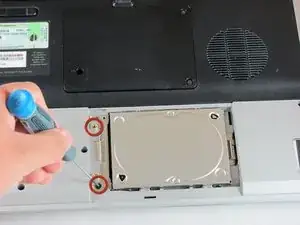
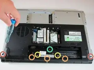
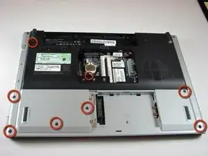
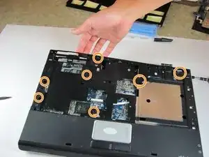
Remove the two 11.0mm screws at the corners on either side of the battery compartment.
-
Remove the three 6.0mm screws.
-
Remove the two 5.0mm screws.
-
Remove the 6.0mm screw in the middle of the battery compartment.
-
-
-
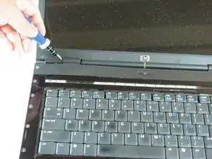
Turn the computer over and open the screen. This provides access to the screen hinges.
-
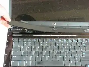
The keyboard switch cover is attached to the computer with a series of snaps. With a flathead screwdriver, pry up the switch cover until it pops free.
-
-
-
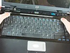
Next, remove the keyboard. Push on the keyboard frame above the function keys and slide the keyboard toward the screen.
-
-
-
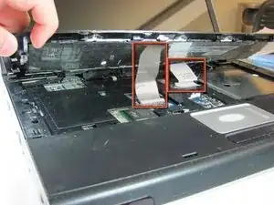
Carefully lift the trackpad-side edge of the keyboard to reveal the LED and keyboard cable connectors.
-
Detach the cable connectors from the computer by gripping each cable connector close to the computer contact point and pulling up gently.
-
-
-
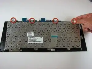
Lay the keyboard face down.
-
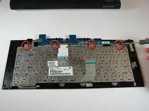
Remove the four 3.00mm screws that attach the keyboard to the keyboard frame.
-
-
-
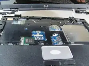
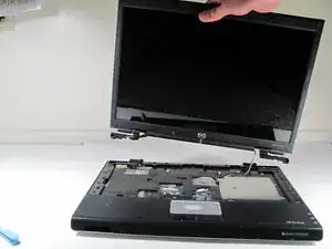
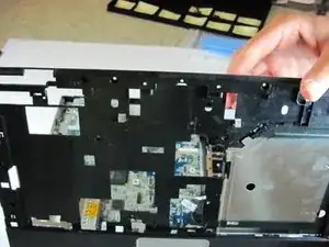
Separate the screen from the computer frame by lifting the screen straight up.
-
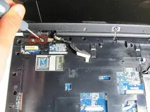
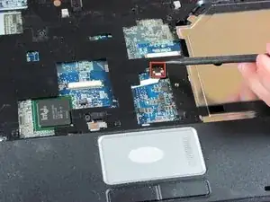
Disconnect the PCI wires by pulling them free of the computer.
-
-
-
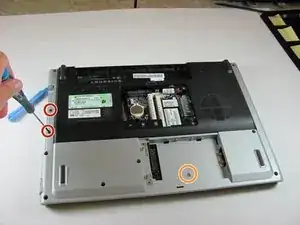
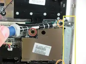
Flip the computer over to access the screws on the underside of the frame.
-
Remove the two 3.0mm screws.
-
Remove the 5.0mm screw.
-
-
-
Flip the computer over so the touchpad is accessible.
-
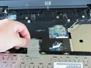
Disconnect the touchpad cable by pulling on it gently.
-
-
-
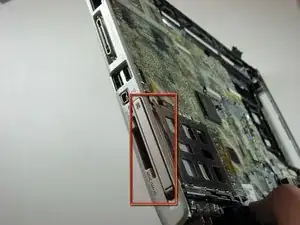
Press gently on the textured front of the Express Card, then release it. It will pop out of the slot.
-
Remove the Express Card from the Express Card slot.
-
-
-
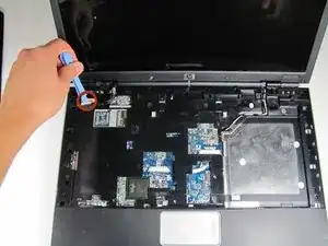
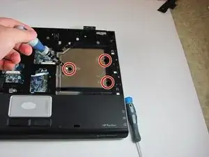
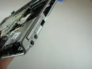
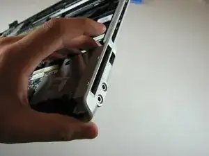
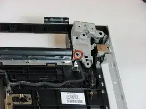
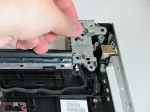
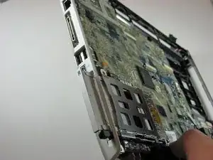
Remove the 6.0mm screw that secures the display hinge support to the computer frame.
-
Remove the display hinge support.
-
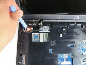
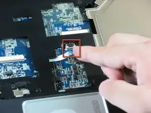
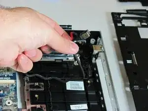
Disconnect the power connector cable.
-
-
-
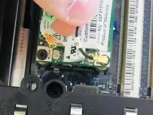
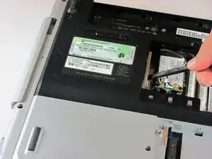
Press gently on the front of the wireless card, then release it. It will pop out of the slot.
-
Remove the wireless card from the wireless card slot.
-
-
-
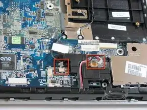
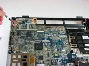
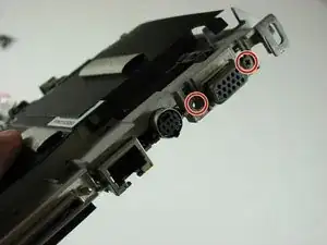
Remove the 10.0mm screw.
-
Remove the two 6.0mm screws securing the Express Card bracket.
-
Remove the Express Card bracket
-


To reassemble your device, follow these instructions in reverse order.
2 comments
Kılavuzu hazırlayan arkadaşa çok teşekkür ediyorum gayet açıklayıcı ve güzel olmuş.
Thank you so much my friend that is perfect.
ycltrn -
Kindly add this on dv 4000 also