Introduction

If your JBL Flip 6 speaker is experiencing persistent issues such as no power, malfunctioning buttons, or a failure to connect via Bluetooth, the root cause may be a faulty motherboard. The motherboard is the central component that controls all of the speaker’s functions, and a damaged or defective motherboard can lead to a wide range of problems that cannot be resolved through simpler fixes.

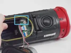
Before beginning this replacement guide, check for any visible signs of damage, such as cracks, burn marks, or loose connections on the motherboard. If the speaker has been exposed to moisture or physical impact, these could be potential indicators that the motherboard needs replacement.

Before starting, power off the speaker and disconnect it from any cables or charging sources to avoid electrical shock or further damage during the repair process.

  1. FncscQJKOvCe3FHr
    FncscQJKOvCe3FHr
    stWeTycONeEAwnaL
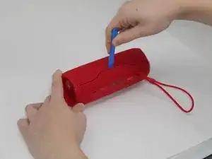
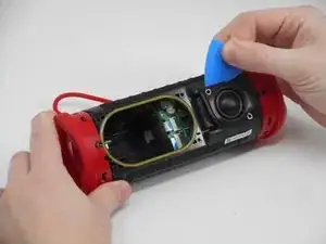
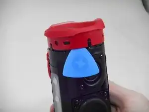
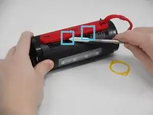
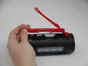
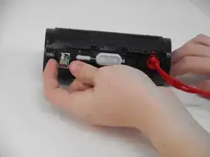
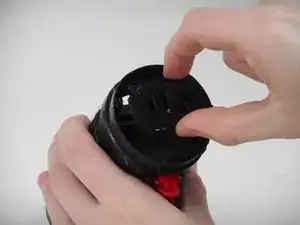
    • Using the iFixit opening tool, pry up on the button side of the slot on the case until the clips release.

  2. I5c2hmR5gMvFmSYJ
    I5c2hmR5gMvFmSYJ
    ZXCf1uL6RnjBf3Rl
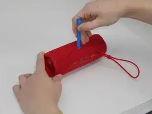
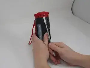
    • Now that the gap is larger, using the same tool, pry up on the other side until the clips release.

  3. YZ52ogJuaYNMBi2m
    YZ52ogJuaYNMBi2m
    hcKEdD2sCZj2bjK6
    dZpZU16QLseAkLqu
    • With all clips released, slide the case off longways.

    • You may need to spread it a bit with your hands so that the clips do not become caught on the end pieces.

  4. FYfYKTJIhfBB5WPl
    FYfYKTJIhfBB5WPl
    YxaWRVyVdEU1T2fd
    • Remove the two 9.5-mm Philips #1 screws securing the tweeter to the device.

  5. uxP2FQYeDgQSKKTt
    uxP2FQYeDgQSKKTt
    PRcDOeSHo2eKZBS5
    AqQYyYGkhlQhvedh
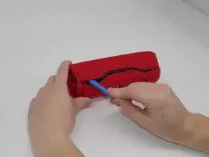
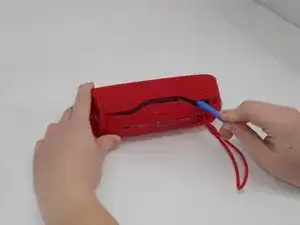
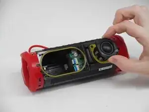
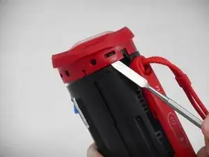
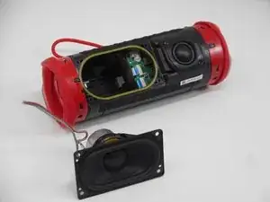
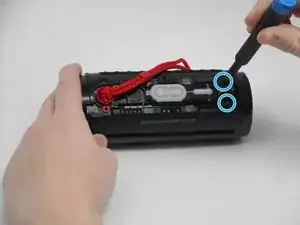
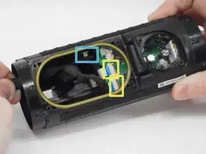
    • Insert an opening pick into the gap along the edge of the tweeter.

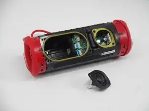
    • Push the tip inwards and pry upwards to release the tweeter from the motherboard.

    Where is the flip 6 tweeter available?

    Siddhant Dube -

  6. ANXXVJ3TGpLVEKRo
    ANXXVJ3TGpLVEKRo
    ZimgrK4JloPtvhHB
    • Use a prying tool to lift up on one of the clips that holds the radiator in place.

  7. JcqKbaoJyJTD2kZi
    JcqKbaoJyJTD2kZi
    CAuk13aI1JCFxTlL
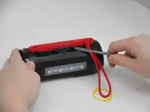
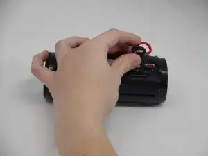
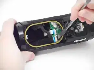
    • After the clip has been released, insert a shim to keep the parts separated and from the clipping back together.

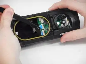
    • Pry on the clip on the other side to fully release the passive radiator.

  8. 51lTRDQrkNkMlelV
    51lTRDQrkNkMlelV
    Jc4I5tRVBhZPOjZ5
    Zntf4MGQxF6MFxP4
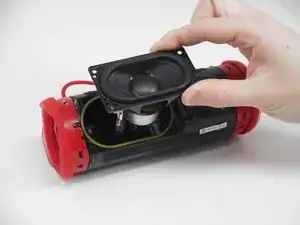
    • After both clips have been detached, the passive radiator is easier to remove by hand.

    • Repeat the same steps for the passive radiator on the other side.

  9. 1U2lRnMu6rinEWlZ
    1U2lRnMu6rinEWlZ
    CIIUkwP2iTVy1wsq
    sekTbnQOtlmnqd1S
    • Remove the four 9.5 mm Philips #1 screws securing the woofer to the device.

  10. DlJqprpWWo6CgZOl
    DlJqprpWWo6CgZOl
    QuBF5BcaGSm5pBNy
    1xi45yDG3QqtL5Si
    • Carefully disconnect the white connector linking the woofer and the motherboard.

    • If there is a lot of resistance when removing the plug, there could be a clip holding it in place. Check for any sort of fasteners before using much strength as you could damage the motherboard.

  11. vNutAvEF4f1VOhHe
    vNutAvEF4f1VOhHe
    IrBsn1EqNBmdksMH
    • Use a spudger to release the clips attaching the cover for the buttons and charging port.

    • After the two clips are removed, the cover can be removed easier by hand.

  12. kwATClMlyCdvZZJO
    kwATClMlyCdvZZJO
    yVZBgCC122hAscqE
    • After the clips have been released, take the cover off, feeding the strap out of the hole.

  13. MvnVbFArjVXLwNK4
    MvnVbFArjVXLwNK4
    ORxHbNIFYAyhIpcr
    pnkUdJuqQBldCK4i
    • Remove the two 5.7 mm Philips #00 screws holding the charging port cover in place.

  14. VQPMaWQYZcpK2VHk
    VQPMaWQYZcpK2VHk
    GvPqUf6iIyHXyORZ
    PrGnQTlSLmiYMoSb
    • Using tweezers, pull the blue ribbon from the connector from the charging port board.

    • After the ribbon is removed, pull the USB-C port out from the outside.

  15. 25JTlJtNqaf1TDDG
    25JTlJtNqaf1TDDG
    EJEpBnBT4CSUDWA4
    oqeHRyBGaKTMFVxk
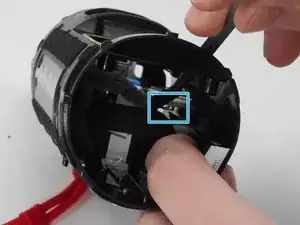
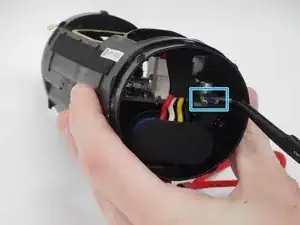
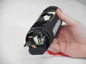
    • Carefully pull the small ribbon cable from its slot.

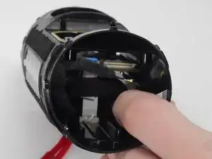
    • Lift up on the black locking flaps opposite the ribbon cables, then carefully pull the ribbon cables out of their slots.

  16. mMrCH33KZPAsyX1N
    mMrCH33KZPAsyX1N
    RT1LDVATayxeJYAF
    • Carefully disconnect the small ground connector from the motherboard.

    • When reattaching this connector, it can be tricky to line up and get it to set. The best way to do it is to position the wire with your non-dominant hand, then, using tweezers, pinch the topside of the motherboard and the connector.

  17. bdBhEsM3YxC2AQd5
    bdBhEsM3YxC2AQd5
    ylJMGGJcbOdFdR6Z
    jucyyvRCAjyoH112
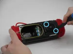
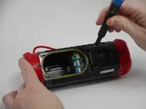
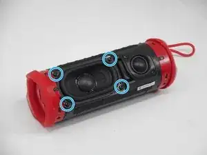
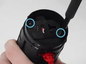
    • Remove the two 9.5 mm Philips #1 screws securing the plastic retainer for the battery and motherboard.

  18. LTrLvoI5moBTuxjm
    LTrLvoI5moBTuxjm
    Qr31xBESGdAOUyka
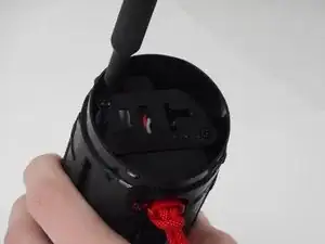
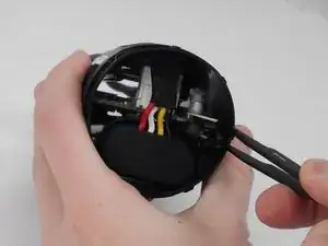
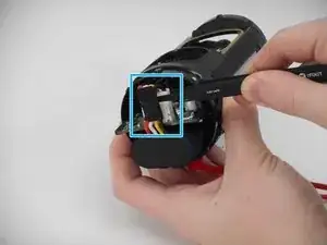
    • Pry up on the black tab, then carefully pull the connector from its port on the motherboard.

  19. fGCBbWn3RCFqEROQ
    fGCBbWn3RCFqEROQ
    qPW1v3yS3WXvdygN
    3uZktEcS6Iuyo2Zy
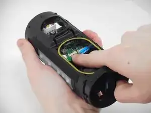
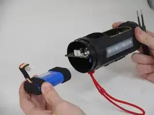
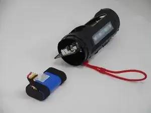
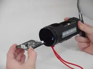
    • Push on the inside edge of the motherboard until the battery connector is outside of the device case.

    • Pinch and pull up on the battery connector to release it, freeing both the motherboard and the battery for removal.

  20. WbFSoLyquMMrWsJK
    WbFSoLyquMMrWsJK
    RkQRcslmj4EwOBey
    2tDkvrNlJW33VxHY
    • Pull out both the battery and motherboard, and repair or replace as needed.

Conclusion

To reassemble your device, follow these instructions in reverse order.

Cody Chamberlain

Member since: 25/09/24

414 Reputation

0 comments