Introduction
Before using this guide, look at the JBL Tune 510BT headphones troubleshooting page for simple solutions to this problem. If none of these simple solutions work, consult this guide to fix your headphones.
This guide is designed to help you replace the damaged LEDs on your JBL Tune 510BT headphones. If you have noticed that the indicating light on your headphones isn't activating or the colors have become dull, this guide will provide step-by-step instructions to help you restore your headphones to optimal condition.
The LED on the headphones is quite useful for headphone use. It allows the user to know if their headphones are powered on if they need charging, and understand if the headphones are in pairing mode. Without fully functioning LEDs, it can be extremely difficult for the user to use the headphones.
-
-
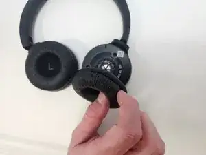
Firmly grasp the earmuff and pull away from the center until the lip of the earmuff is disengaged.
-
Pull the earmuff towards the center of the headphones until it is free.
-
-
-
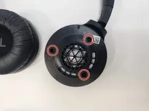
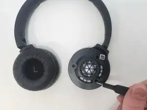
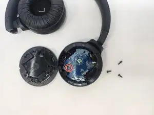
Carefully remove the faceplate by lifting it firmly.
-
To completely detach the faceplate, desolder the wires from the connections on the motherboard.
-
-
-
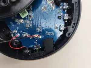
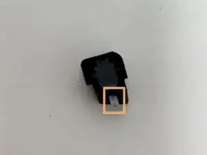
This is where you would find the rubber housing normally.
-
If the rubber housing is dislodged, which is fairly common, simply replace it in its correct orientation to its seating, being sure to place the indicated piece through the hole to the exterior of the headphones.
-
-
-
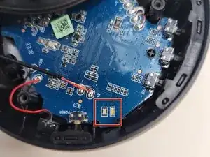
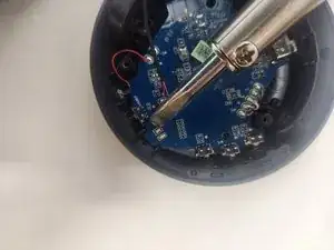
Heat the small spots of solder where the two LED strips are on the circuit board with a soldering iron.
-
Solder the new LEDs into position, making sure the contacts are solid.
-


To reassemble your device, follow these instructions in reverse order.