Introduction

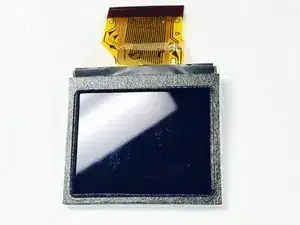
This guide will outline the step-by-step process of replacing the LCD screen of the JVC Adixxion GC-XA1BU.

  1. 4shyQt5amun1eDKJ
    • Find the side of the camera with the black switch shown.

  2. B2Ja4KpkSs213ws4
    • Push down on the black switch.

  3. UuBMOoDQ5IxWHGIb
    • Slide the battery cover back while pushing down on the black switch.

  4. G2BFqCBcMlljvPYA
    G2BFqCBcMlljvPYA
    MQiOEgZhZbvEMgkx
    • Open the battery compartment and push the blue battery release switch.

  5. XlJHBBAkLQ4jSR4x
    • Remove the battery from the camera.

  6. oDbfFbEEE252AewQ
    • Remove the two Phillips screws (4mm x 3mm) using the Phillips #00 screwdriver.

  7. Yfy2QoqCVJMpRpIV
    Yfy2QoqCVJMpRpIV
    kVwDLeuE1PmrPtx2
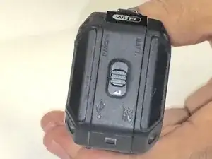
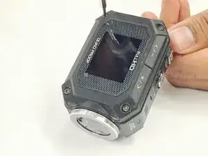
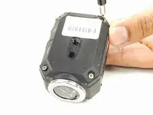
    • Remove the 8 screws (5mm x 4mm) from the corners of both the front and back of the camera (4 screws on each side) using the T6 Torx screwdriver.

  8. tigebEgbvvlHbxMi
    • Carefully open the camera as shown and gently peel off the black cover tape.

  9. GZCaCBhFhBgRXNu4
    GZCaCBhFhBgRXNu4
    IJlv2skKDewADkal
    sTYM2WNTKfEEsDOQ
    • Carefully lift up and remove the cable ribbon clip using the tweezers.

  10. 4jIwC6jRLGfUD6on
    4jIwC6jRLGfUD6on
    KLpk2sRIvjlR12EZ
    • Carefully grasp and remove the ribbon cable using the tweezers.

  11. DCO1vgcRJwgreXEW
    • Turn the camera as shown and carefully remove the glue from the connector.

  12. WFoPKxSRX6pE5nNX
    WFoPKxSRX6pE5nNX
    w5oj5QhQIcjd5uHS
    • Carefully pull the white clip out of the casing using the tweezers.

  13. F5kmMWnqAnHLETNy
    F5kmMWnqAnHLETNy
    tDVLEliB5nLxK5qL
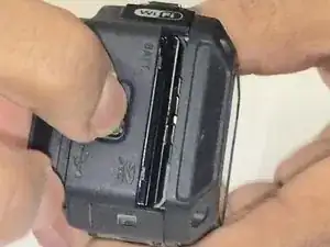
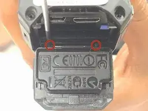
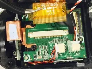
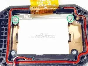
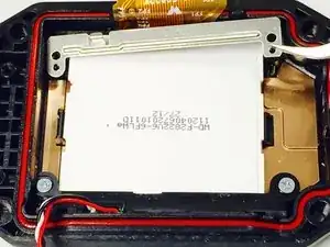
    • Use a Phillips #00 screwdriver to remove the two top screws (4mmx x 3mm). Once the screws are removed, carefully lift off the silver plate using Tweezers.

  14. hIHMDwgJGW3HRIhe
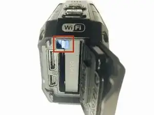
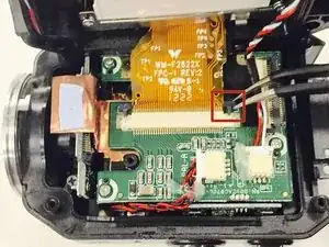
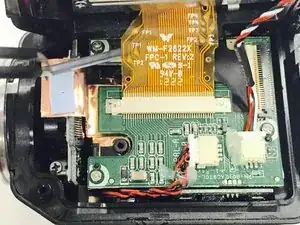
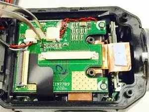
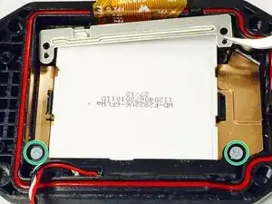
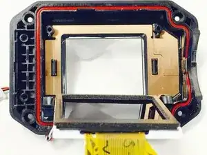
    • Once you have lifted and removed the silver plate, use a Phillips #00 screwdriver to remove the two bottom screws (4mm x 3mm).

  15. GNplKLM3MhgTUVt6
    GNplKLM3MhgTUVt6
    R5ocv4xFFXV1ZoTx
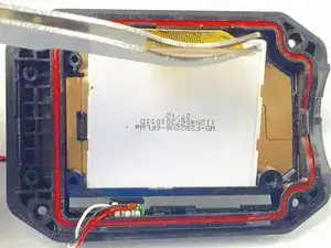
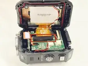
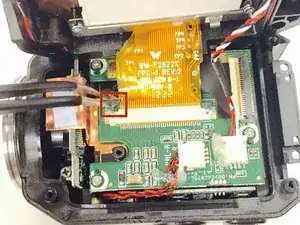
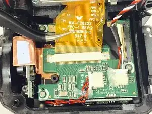
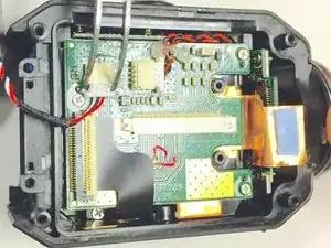
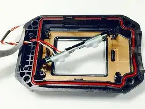
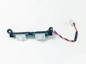
    • Using Tweezers, gently pull the red, black, and white threaded wire to disconnect it, then remove the attached panel as shown.

  16. RXELv6wSEHNVVTtF
    RXELv6wSEHNVVTtF
    Noxw251iJtG14Kge
    • Carefully lift up and remove the LCD screen using the tweezers.

  17. rhl1YwaiB3eR2DgA
    rhl1YwaiB3eR2DgA
    v4HbL3XRbZHV3g1f
    • The screen as shown if removed properly.

Conclusion

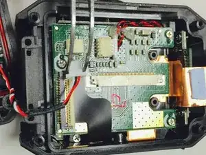
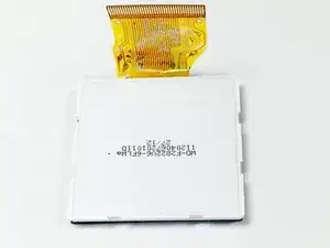
Follow these steps in reverse order with the new LCD screen in order to complete the replacement.

Christina Michelle Johnson

Member since: 16/01/15

1047 Reputation

0 comments