Introduction

If the zoom (+/-) buttons on your JVC Adixxion GC-XA1BU action camera are unresponsive, stuck, or damaged, replacing them may be necessary to restore full functionality. However, before proceeding with a replacement, it is important to troubleshoot the issue.

If the buttons are unresponsive, check if the camera's firmware is up to date and restart the device to rule out software issues. Make sure there are no dust or debris that may be obstructing the buttons. If the buttons are cracked, missing, or not clicking properly, a replacement is needed.

If troubleshooting does not resolve the issue, follow this guide to safely and effectively replace the zoom (+/-) buttons on your JVC Adixxion GC-XA1BU.

  1. 4shyQt5amun1eDKJ
    • Find the side of the camera with the black switch shown.

  2. B2Ja4KpkSs213ws4
    • Push down on the black switch.

  3. UuBMOoDQ5IxWHGIb
    • Slide the battery cover back while pushing down on the black switch.

  4. G2BFqCBcMlljvPYA
    G2BFqCBcMlljvPYA
    MQiOEgZhZbvEMgkx
    • Open the battery compartment and push the blue battery release switch.

  5. XlJHBBAkLQ4jSR4x
    • Remove the battery from the camera.

  6. oDbfFbEEE252AewQ
    • Remove the two Phillips screws (4mm x 3mm) using the Phillips #00 screwdriver.

  7. Yfy2QoqCVJMpRpIV
    Yfy2QoqCVJMpRpIV
    kVwDLeuE1PmrPtx2
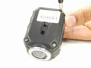
    • Remove the 8 screws (5mm x 4mm) from the corners of both the front and back of the camera (4 screws on each side) using the T6 Torx screwdriver.

  8. tigebEgbvvlHbxMi
    • Carefully open the camera as shown and gently peel off the black cover tape.

  9. GZCaCBhFhBgRXNu4
    GZCaCBhFhBgRXNu4
    IJlv2skKDewADkal
    sTYM2WNTKfEEsDOQ
    • Carefully lift up and remove the cable ribbon clip using the tweezers.

  10. 4jIwC6jRLGfUD6on
    4jIwC6jRLGfUD6on
    KLpk2sRIvjlR12EZ
    • Carefully grasp and remove the ribbon cable using the tweezers.

  11. DCO1vgcRJwgreXEW
    • Turn the camera as shown and carefully remove the glue from the connector.

  12. WFoPKxSRX6pE5nNX
    WFoPKxSRX6pE5nNX
    w5oj5QhQIcjd5uHS
    • Carefully pull the white clip out of the casing using the tweezers.

  13. F5kmMWnqAnHLETNy
    F5kmMWnqAnHLETNy
    tDVLEliB5nLxK5qL
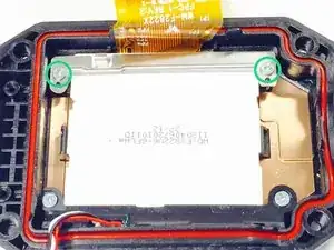
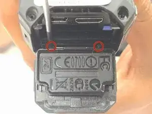
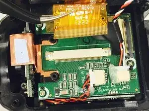
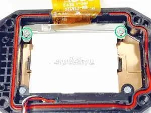
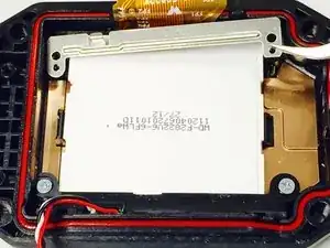
    • Use a Phillips #00 screwdriver to remove the two top screws (4mmx x 3mm). Once the screws are removed, carefully lift off the silver plate using Tweezers.

  14. hIHMDwgJGW3HRIhe
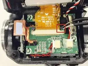
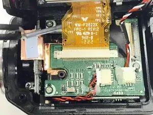
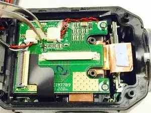
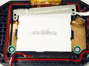
    • Once you have lifted and removed the silver plate, use a Phillips #00 screwdriver to remove the two bottom screws (4mm x 3mm).

  15. GNplKLM3MhgTUVt6
    GNplKLM3MhgTUVt6
    R5ocv4xFFXV1ZoTx
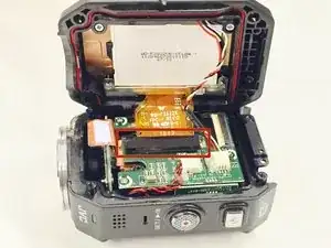
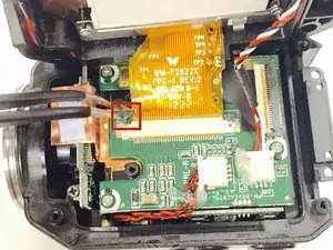
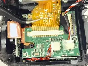
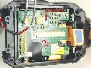
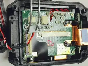
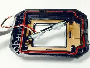
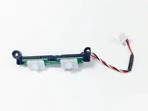
    • Using Tweezers, gently pull the red, black, and white threaded wire to disconnect it, then remove the attached panel as shown.

Conclusion

To reassemble your device, follow these instructions in reverse order.

Christina Michelle Johnson

Member since: 16/01/15

1047 Reputation

0 comments