Introduction
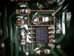
This instruction describes the disassembling of the device head of the wet vacuum cleaner. The attached video shows defect of the control board. Crackle sounds and an exchanging sparke illustrates the defect. In addition, the motor doesen't speed up. As source a resistor on the control board could be identified. This one is suppling an IC-Part on the circuit board with voltage. Expirience in soldering is mandatory.
Tools
Parts
-
-
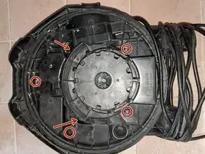
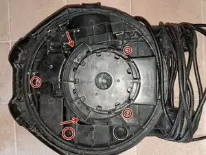
Underneath the device head are 6 Torx TX25 screews. Screew out these.
-
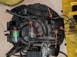
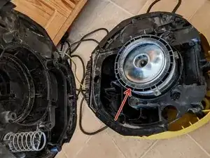
Then the device head can be disassembled in to 3 main parts. While pulling the pieces apart act gentle. Espacially because the motor is sanwitched by the housing parts and the grouding cable has to be pulled off. Furthermore the cable length from the board is short and shouldn't be stressed by pulling.
-
-
-
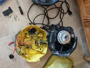
The PCB is clampt into the housing halves and disangages while disconnecting the parts. The control knob can disengaged by pressing the detents togehter with pliers. Then the knob can be pulled out.
-
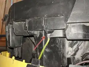
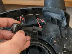
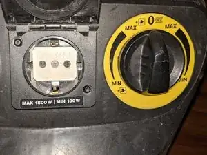
The socket - for the remote startup of the vacuum - can be pulled out as well by pulled out by screew out 2 Torx TX20 screews. This is not mandatory but thats recommended for easier assembling. Especially for realising squeezing cables.
-
-
-
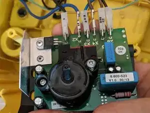
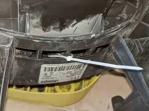
Before pulling out the plug contacts mark them for simply recontecting them afterwards (e.g. 3 dots on the plug of X3). Then disconect them.
-
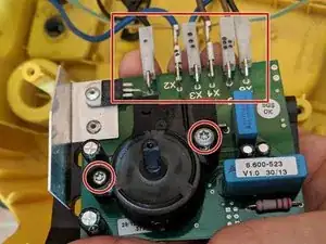
There are two Torx TX25 screws to disengade. They hold a plastic part on the bottom side. In a younger version the plastic part on the bottom side is only clipped.
-
-
-
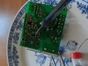
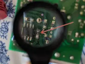
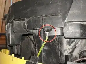
With chilled hand soldering the resitor can be extracted. A pair of tweezers or a tip of a knife can be helpful to lift it up.
-
Solder in new part.
-
It is recommended to use an air suction while soldering. In addition a magnifier and a professional soldering system is helpful and a desoldering pump is gold.
-
-
-
Attach the plastic part back to the PCB. Put the plug contacts on the sockets.
-
Use the plastic part from the PCB to clamp it to the right position at the housing.
-
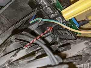
While reassembling the housing parts it is possible to observate the position of PCB through the socket hole.
-
-
-
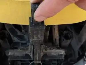
The filter cleaning flap is layed in only and will be hold in place by two housing parts pressed together. Because of that it is recommended to use cable ties to stick it in position. Doing this even the spring can't be lost.
-
-
-
Attach the socket with two TX20 screews and put the operating knob back in.
-
Remove cable ties by wire cutter.
-
Replacing the resistor, who costs about 4 euro cent prevents you from buing a new PCB, that costs of 90-100€. Unfortunatly, the motor got no protection by a fuse or something else to prfenvent a overload on the PCB board.

9 comments
Hallo,
kurze Rückmeldung vom Ersteller. Die Abschaltung nach ca. 3sek. bei der Fernsteuerung des Saugers durch ein externes Gerät funktionierte nach der Reparatur nicht mehr. Das heißt wer diese Funktion weiterhin nutzen möchte, muss wissen ob Ihm das 100€ für die Ersatzplatine wert ist.
Grüße
Vielen Dank. Ohne diese Anleitung hätte ich meine Reparatur nicht geschafft. Man muss unbedingt darauf achten am Ende den Kabelbinder wieder zu entfernen sonst kann es sein dass der Sauger nicht richtig zieht. Mir hat diese Anleitung beim Zusammenbau den Hintern gerettet.
Falls jemand beim Versangen von WD3, WD4,WD5, WD6 ähnliche Probleme Hat: LM358 oder LM258 kann statt dem deffekten Microchip gelötet werden. Löterfahrung vorausgesetzt, natürlich. Und damit es nicht wieder eine Lötaktion wird, gleich Dip8 dran löten, wie in diesen Video:
https://www.youtube.com/watch?v=ACNQbUNU...
Danach gerne die Lötpunkte Isolieren (Heißkleber) und ggf. ein Kühlkörper auf LM drauf
Zonder overzicht van gereedschappen, had ik mijn reparatie niet kunnen doen, waarvoor hartelijk dank.
Jos Lange -