Introduction
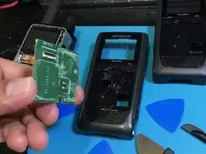
This Kenwood Handheld VHF/UHF Triband 144MHz/220MHz/440MHz presented with a unit that has been dropped or thrown inadvertently during a house move. The charger cord is missing also. I began with a broken face plate radio, dead battery, and charger base with missing power cord. The unit was restored, reprogrammed and made operational/ usable again.
-
-
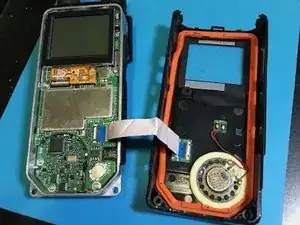
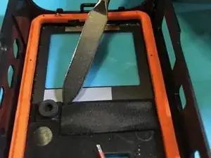
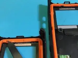
The faceplate has locks to the rear plastic panel on the topmost margin. The bottom part is secured by two philips-head screws. There is an obvious white ribbon connector that must be carefully removed from both ends. The connection is held by a hinge clip. You pick the hinge to raise it up and release the cable end.
-
-
-
The plastic tool (seen on R side) is able to pry up the hinge lock that holds the ribbon end to the connector block. Use your fingernail to aid the plastic tool in releasing the hinge lock from pressing on the cable.
-
-
-
Remove the soft foam padding and the microphone foam tube from the old faceplate. It is glued but can be lifted off with care. Use tiny amounts of cyanoacrylate (Super Glue) to reattach them to the new faceplate
-
-
-
There is a metal spring that is located on top of the rubber seal that appears to function as an antenna component (maybe a counterpoise) or just a spring lock. Need to transfer this too by prying it out carefully. It is 1.5 inches long
-
-
-
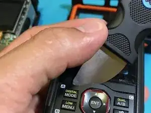
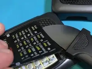
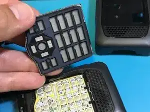
Start prying out the keypad sheet using the wide metal pick. The glue is a thin line in the periphery of the keypad
-
-
-
Continue prying carefully and it will reveal the multi-switch board underneath (with copper terminals)
-
-
-
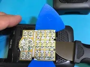
Be carful with this switch or keypad electronic board. Use the plastic picks to aid in lifting the board with progressive lifting from all sides.
-
-
-
The copper lined switchboard is glued on to the plastic front panel and but be dissected thru using the plastic black tool. Keep inserting the blue picks to maintain distributed pressure to lifting off the board. DO NOT use a metal tool here
-
-
-
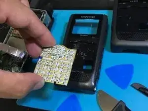
Switchboard removed completely. DO NOT bend or press on any button while the board is off the plastic panel. This is a thin and sensitive board.
-
-
-
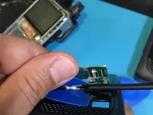
This is the underside of the switchboard. Notice the contacts for the speaker and the ribbon connector block
-
-
-
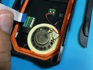
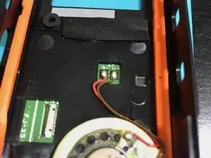
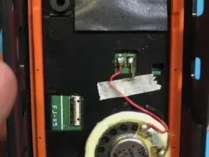
Reconnect the speaker terminals. Wire with black stripe goes to the negative terminal (right side on the photo). Use a small paper tape to keep the wires tidy. NOT IN PHOTO, reconnect the ribbon connector cable. Test the sound, and keypad before locking the faceplate back to chassis
-
-
-
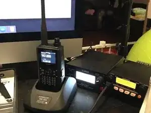
Program the frequencies, PL tones, test at low power to reach the repeater; or use 146.52 simplex to test with another radio. Good luck!
-
To reassemble your device, follow these instructions in reverse order.
2 comments
Half of this repair is missing and the grammar is awful. Remove this tutorial. It says nothing about putting the radio back together. Ridiculous.
I can understand that your title is Fake Newspapers… that is EVIL to me to begin with commenting on your comment. Second, this is a community of positive support, I uploaded half of it, try to add the next half if you figure it out. There was NOTHING before I uploaded this. The grammar got distorted in the upload process, why don’t you correct them and improve the grammar? You attitude is despicable as a third comment. You are likewise ridiculously awful to be in this community. I did not learn anything good from you today. Get out of here.
Jojo -