
Introduction
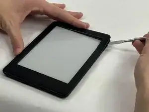
The mini-USB charging port may become loose due to force such as removing the charging cable too forcefully or dropping or shaking the Kindle 10. You will know the charging connector is loose if you read this troubleshooting page. This guide will help you solder the connection or replace the mini-USB charging port altogether.
-
-
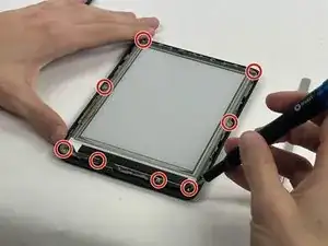
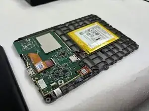
Remove the two outer silver screws with a T5 Torx screwdriver.
-
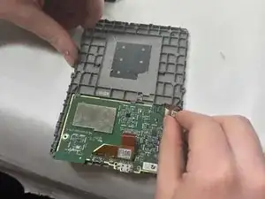
Use your fingers to remove the two gold screws in the middle.
-
-
-
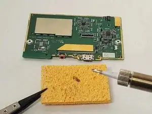
Turn on the soldering iron.
-
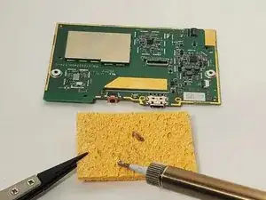
Clean the tip after old solder has melted by dragging it across a sponge.
-
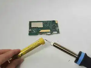
Prime the soldering iron by touching its tip with a dab of lead-free wire. Your soldering iron is ready when the solder readily melts.
-
-
-
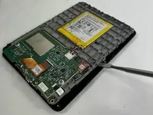
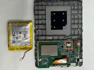
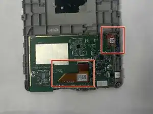
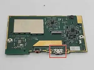
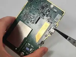
The charging port is located to the right of the button and status light. The motherboard is facing up in the photo, as indicated by the silver block of memory on the upper left.
-
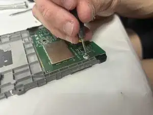
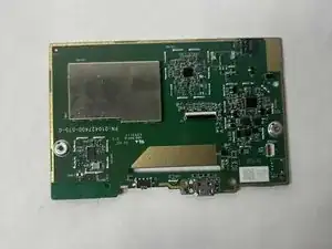
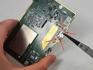
Desolder the four connections on the back of the motherboard behind the charging port by holding the tip of the hot soldering iron to each connection.
-
If you are replacing the charging port, remove the charging port component with a pair of tweezers.
-
If you want to reinforce the soldering joints without replacing, just hold the tip of the soldering iron to each connection with a bead of melted lead-free solder wire.
-
-
-
Search for "Through-Hole Soldering" on this How To Solder guide to ensure you replace and solder the charging port correctly.
-
If you are just improving the connection and not replacing the component, skip this step.
-
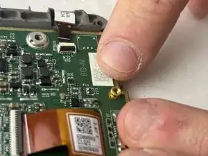
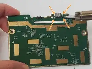
Pull the wires on the four sides of the replacement charging port through the holes in the circuit where the charging port was previously.
-
Solder its joints in the back. Be sure that the soldering joints creates a concave tent shape indicating a strong connection.
-


To reassemble your device, follow these instructions in reverse order.
