Introduction
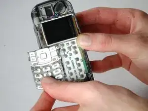
The LCD screens are connected as one unit, and therefore should be removed together.
Tools
-
-
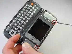
Remove the two triangular pads at the top of the two speakers.
-
These pads have adhesive to keep them situated, so you may want to use a fine-tipped object, such as a screwdriver or a pen, to remove them. It is easiest to place the fine-tipped object in the small indent in the corner of these pads.
-
-
-
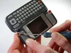
Remove the two rubber cylinders from their shafts. These cover more screws.
-
This requires a little more effort, so you may need to "dig" them out.
-
-
-
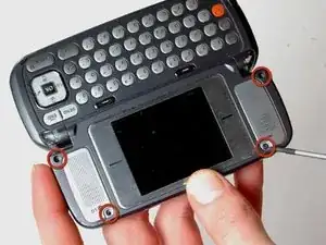
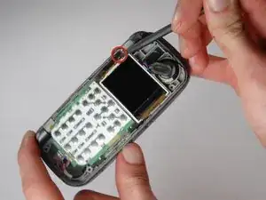
Starting on the side with red square, pry the faceplate upwards with the flat end of a spudger.
-
Continue to slide the flat edge along the seam of the faceplate.
-
-
-
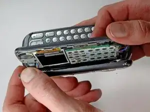
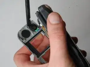
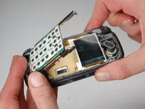
Lift the dislodged faceplate off the motherboard while being mindful of the wires still attached to it.
-
-
-
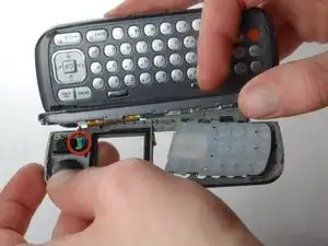
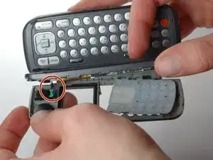
The faceplate is still attached through speakers that travel from the ear-piece to the motherboard.
-
Carefully wedge the flat or pointed end of the spudger beneath the ear-piece and the faceplate.
-
This may require a bit of force, as the ear-piece is stuck to the faceplate with adhesive.
-
-
-
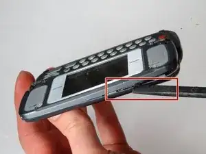
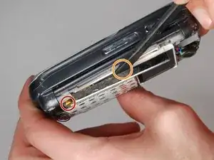
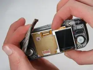
Wedge the spudger into the small gap between the phone and the metal casing of the motherboard.
-
Slide the spudger underneath the metal and along the edge. The motherboard should begin to rise.
-
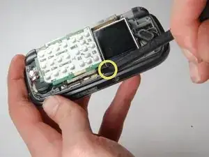
Now use the spudger to lift the other side of the motherboard.
-
-
-
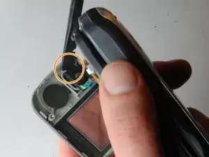
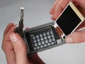
Gently pull the LCD screen upwards.
-
Remove the speaker wires from the LCD screen.
-
Replace the LCD screen and solder the wires to the new screen.
-