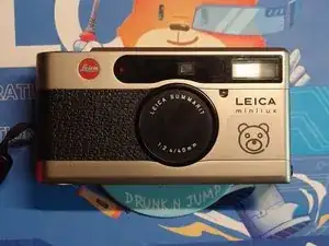
Introduction
Before You Begin:
- Remove the battery and film from the camera.
- Consider recording the entire repair process with a phone or video camera.
Important Notes:
- Do not use excessive force when disassembling parts.
- Avoid touching the circuit board, especially the flash capacitor, as it may retain a high voltage charge. Consider wearing gloves for added protection.
Your Contribution is Welcome:
If you have any suggestions for improving this guide, such as correcting errors or suggesting clearer language, please feel free to share your feedback. Thank you!
-
-
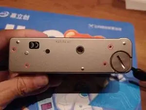
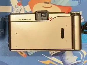
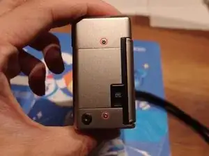
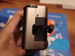
Unscrew: Remove the 4 screws on the bottom case and the single screw on the back near the viewfinder.
-
-
-
Remove bottom case first. Please note the black plastic within the red rectangle. I am uncertain about its original position.
-
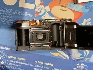
Then remove the top case gently.
-
Lastly, remove the front case.
-
-
-
Unscrew the 4 screws around the lens protection cover, and then remove the lens protection cover.
-
-
-
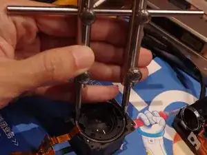
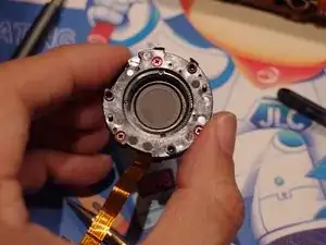
Add some marks on the ring for later reinstallation(This step is unnecessary if the lens barrel and other structures remain unchanged).
-
Use one finger to cover the rectangular area to prevent the spring from flying away. Then, remove the spring.
-
Remove the focus gear.
-
-
-
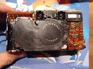
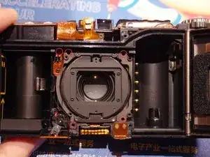
Unscrew the 6 screws to detach the lens module. You can remove the lens module now or later.
-
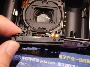
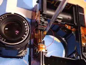
Unsolder the FPC joints.
-
-
-
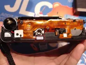
Unscrew the two screws hidden under the FPC and take the FPC out.
-
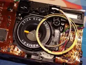
Do not attempt to remove the FPC in the same way shown in Image 2.
-
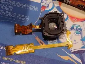
Now the lens module can be taken out.
-
-
-
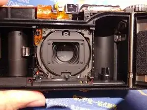
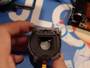
Unscrew the 4 screws securing the rear lens guide. Carefully remove the guide, making sure not to lose the spring that connects the three(or two) pieces. Keep these pieces together.
-
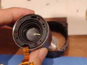
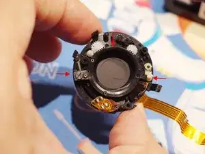
Locate the two contact points on the rear lens rings. You may need a special tool('井') to loosen these points, such as a small screwdriver or tweezers may be okay too(I haven't tried).
-
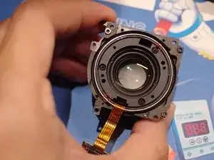
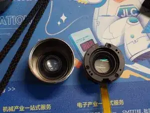
Remove the lens barrel, ensuring that the other two barrels remain in their original positions. Misaligning these barrels can be difficult to correct.
-
-
-
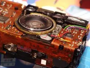
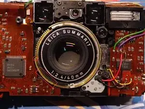
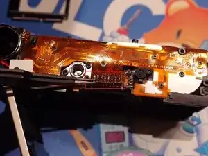
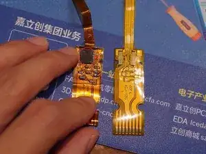
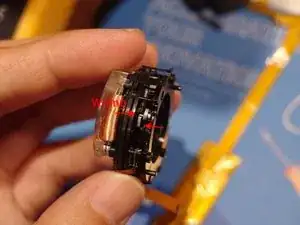
Desolder the existing FPC, paying special attention to the two chips marked with circles, ensuring they both maintain their original orientation. Carefully desolder these chips and transfer them to the new FPC.
-
-
-
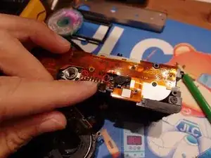
Unscrew 1 screw on FPC, unsolder 4 joints of relays.
-
Unscrew 3 screws.
-
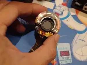
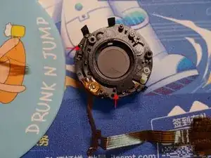
Unscrew 1 screw on FPC, unsolder 4 joints of optocoupler. Be aware the ring and ring position points by arrows. It's easy to fall off, so I keep it as the last step, after completely remove FPC, install the new one immediately.
-
There are some plastic pads stick on old FPC, remove and install them on the new FPC.
-
-
-
First screw rare element group and shutter module together.
-
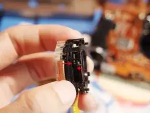
Align the center of the shutter FPC with the notch on the front of the lens barrel. Gently push the lens module back into place. You may hear a click as the rear module locks into position. Slightly rotate the rear module to ensure it's securely locked.
-

To reassemble your device, follow these instructions in reverse order.
With help of Gemini from Google.