
Introduction
A motherboard replacement is necessary when the existing board becomes damaged or stops functioning properly. Common reasons include hardware failures such as power delivery issues, damaged ports or connectors, liquid spills, short circuits, or physical damage from drops or impacts. Additionally, a motherboard may need to be replaced if it has burnt-out components or other irreparable faults that prevent the laptop from powering on or operating correctly. This guide is designed to help users safely replace the motherboard in such situations to restore the device's functionality.
-
-
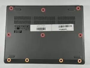
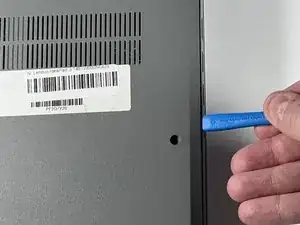
Orient the laptop so that the bottom is facing up.
-
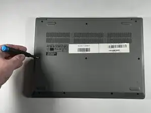
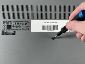
Remove the six 7 mm screws using a Phillips #00 screwdriver.
-
Remove the four 4 mm screws using a Phillips #00 screwdriver.
-
-
-
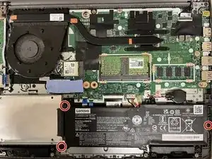
Remove the three 4 mm screws connected to the battery pack using a Phillips #000 screwdriver.
-
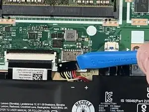
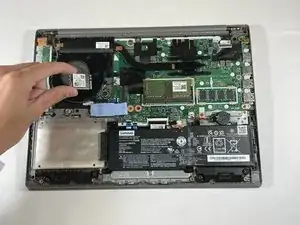
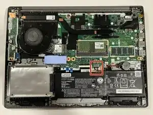
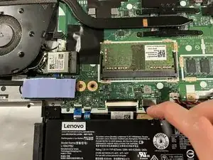
Disconnect the battery cable from the motherboard.
-
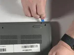
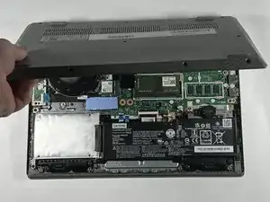
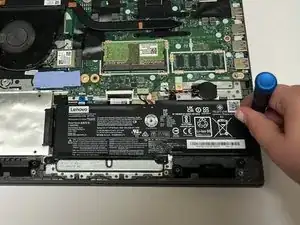
Gently lift up the battery pack by hand to remove it.
-
-
-
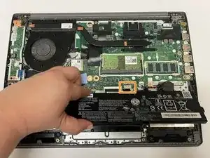
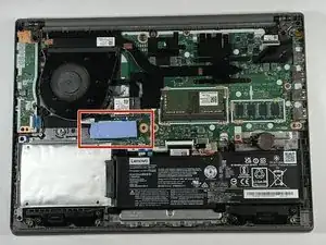
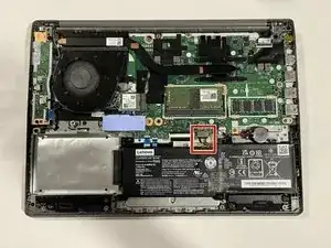
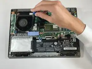
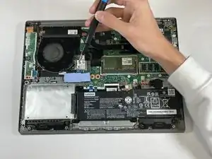
Use your fingernail or an opening tool to gently pull out and disconnect the battery pack cable.
-
-
-
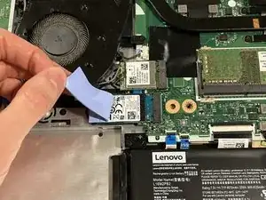
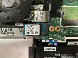
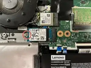
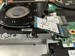
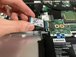
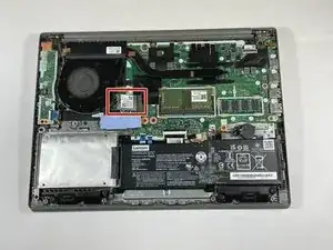
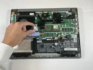
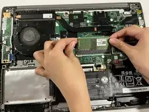
Pull the card away from the housing capsule on the right side of the Wi-Fi card to remove it from the laptop.
-
-
-
Use your fingernail or an opening tool to gently pull out and disconnect the battery pack cable.
-
-
-
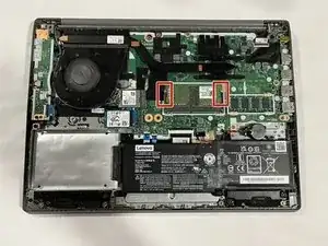
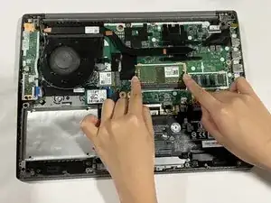
Disengage the latch of the RAM by pushing outwards on the left and right side of the memory module slot.
-
-
-
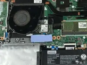
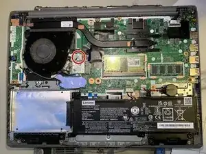
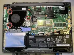
Remove the four 3 mm Phillips screws that secure the heat sink.
-
Gently lift the heat sink up and out.
-
-
-
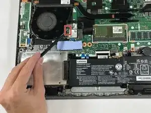
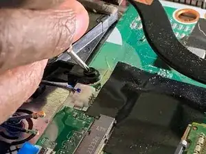
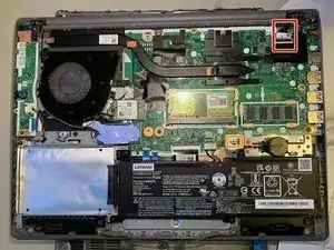
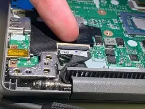
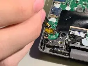
Lift the black ZIF locking flap and disconnect the display connector.
-
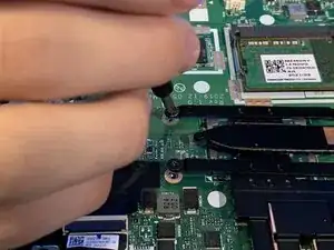
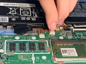
Use your fingernails to gently "walk" the white CMOS battery connector out of its motherboard socket.
-
-
-
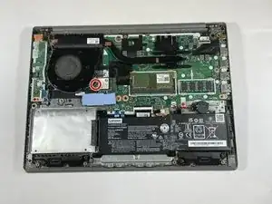
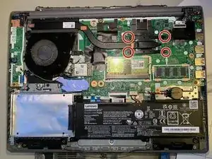
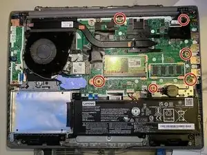
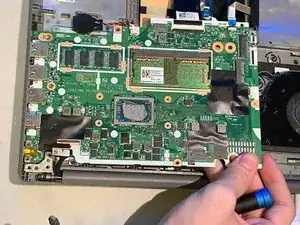
Remove the seven 4 mm Phillips #00 screws securing the motherboard to the chassis.
-
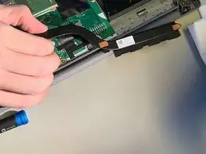
Lift one corner gently. Check for any remaining connected cables, and carefully remove the motherboard out of the case.
-


To reassemble your device, follow the above steps in reverse order.
Take your e-waste to an R2 or e-Stewards certified recycler.
Repair didn’t go as planned? Try some basic troubleshooting or ask our Answers community for help.