Introduction

The motherboard of the Lenovo IdeaPad A1-07 may need to be replaced if the tablet has become unresponsive due to a software issue. Over time the motherboard can degrade from constant use or even crack if under a lot of pressure. This guide will walk you through how to carefully take the tablet apart to access and remove the motherboard from the device.

Before you begin the repair, make sure to power off and unplug your laptop from the charger.

  1. RAoLNcXIHLUT5wKs
    RAoLNcXIHLUT5wKs
    JkNgHXyWN5uDFC3m
    xPmVrMMKVRQNjHJc
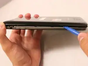
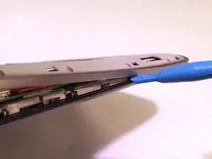
    • With the blue plastic opening tool, use the lock screen switch by the volume button as an access point to gently lift the back cover off.

    • Wedge the opening tool until you start hearing the back cover popping off the body of the device.

    • Slide the opening tool down the length of the device.

    • Once it is about half way off, you can use your thumb to pull the rest of the back cover off.

  2. GRRQCxTD6jxivELE
    GRRQCxTD6jxivELE
    qjREciuPL1nOWvC4
    bSR14Ct14GF1sTYT
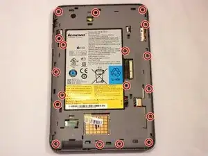
    • Using a Phillips #000 screwdriver, remove all 18 of the 4mm screws.

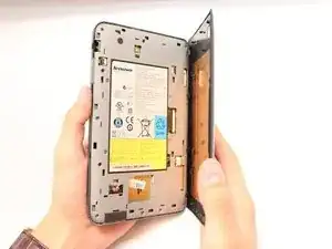
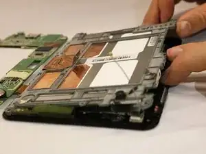
    • With the blue plastic opening tool, gently wedge the tool between the screen and the gray frame until you feel resistance.

    • Do not force the frame off because you can break off the teeth securing the frame to the screen.

    • Using your opening tool, push in the teeth towards the center of the device, and gently pull off the frame.

    • The gray frame will still be connected to the device by a pair of wires from the motherboard to the speaker.

  3. LDtVmQqDldvwohUN
    LDtVmQqDldvwohUN
    vDX6QvmRXml4NWWS
    • The speaker in the grey frame is connected to the motherboard by the white plastic connector.

    • Disconnect the speaker by separating the two sides of the speaker connector.

  4. UsMKED2Y6LIp3vYu
    UsMKED2Y6LIp3vYu
    iEYt6WDV35Njk1PY
    VGKeBvqIuCRGDTRA
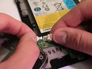
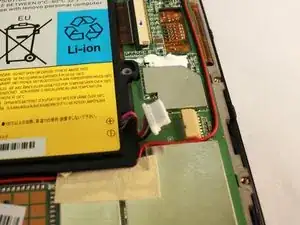
    • Use a plastic opening tool to push the white battery connector out of its socket on the motherboard.

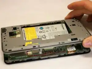
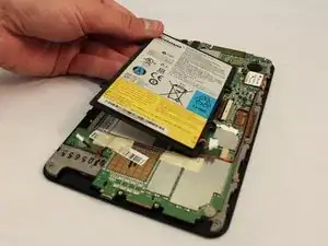
    • Lift the battery away from the device.

  5. RM2RF63dytZnZmN2
    RM2RF63dytZnZmN2
    VD3SAnVUOWpFSLls
    vGMdlfKObFWiVuuR
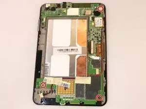
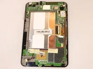
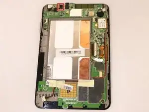
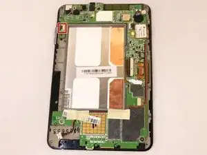
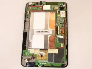
    • Remove the three 3 mm screws holding the motherboard to the screen using your Phillips #000 Screwdriver.

    • You will have to disconnect all the connectors on the motherboard.

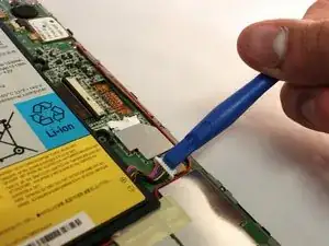
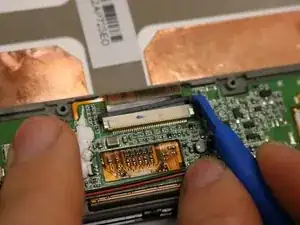
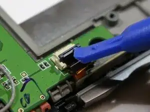
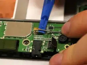
    • Locate the connector in the center of the motherboard and remove it.

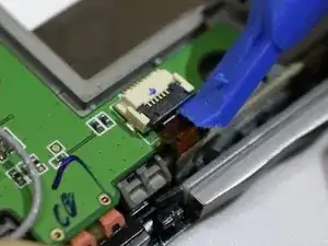
    • Use the opening tool to slide the small black retainer, relieving pressure on the brown ribbon cable.

    • Pull the brown ribbon cable out of the connector with the edge of your opening tool.

  6. RDHBdXUOaWWMHRLi
    RDHBdXUOaWWMHRLi
    raSWLYGUOucTiQTW
    YQeCftYNipJPpRJh
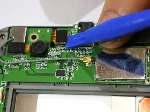
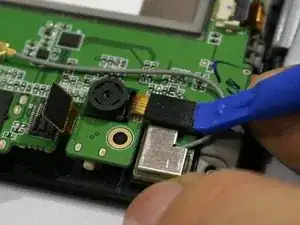
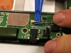
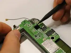
    • Disconnect the connector to the right of the back camera by using a plastic opening tool to lift and pry it up.

    • Once it snaps up out of place, it has been disconnected.

  7. cO2ldcKWAvJfiAOi
    cO2ldcKWAvJfiAOi
    ruSXZnvOnNMoQFTo
    SkhqRJyvZUQGlavd
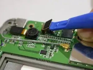
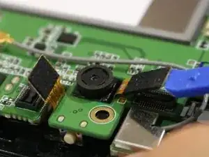
    • Using the same process as the previous connector, disconnect a similar connector to the left of the back camera.

  8. cfDlMIQcIASOLb3l
    cfDlMIQcIASOLb3l
    p53IIs4wXr1fBISJ
    TNFEiEtVDULVAGo6
    • There is a third connector located on the top left of the motherboard, right next to the volume button.

    • Use your opening tool to lift up the black lever on the connector.

    • Pull out the brown ribbon underneath it with your opening tool.

  9. RuQypk5L3gHA1545
    RuQypk5L3gHA1545
    O2hioDE3Oq22a4hJ
    dEVRaXBEQWT6bElF
    • The final connector is a grey cable with a gold tip called the coaxial cable. It's snapped in tightly and may take a little bit of force to disconnect.

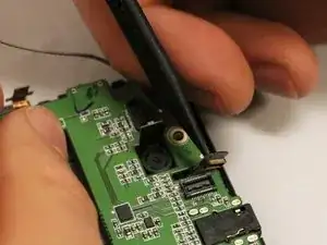
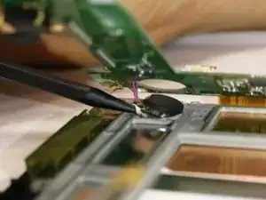
    • Disconnect the last connector by sliding the opening tool up to the base of the tip.

    • Twist the opening tool to gently lift up the coaxial cable.

  10. OeOhGU6Da1fsRPUr
    OeOhGU6Da1fsRPUr
    BqUuuoNS5y2dkjcu
    iGVIVrhINFnYboHM
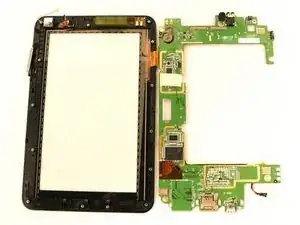
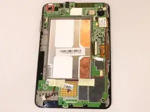
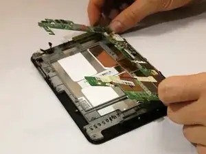
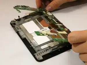
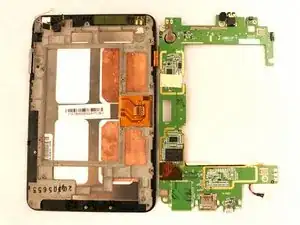
    • Lift up the motherboard, pushing the connector heads back down through the holes they come through

    • With the cameras oriented on top, there will still be one ribbon on the right of the motherboard connected to the screen.

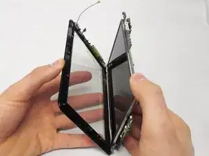
    • Lift the motherboard on the left side and flip it over to the right, like turning a page.

  11. RunRMAUKBYC15n1y
    RunRMAUKBYC15n1y
    HQuISKhUYnSPhy2A
    HG13LJ22tfHHirLS
    • Once all the connectors are pushed through, the last thing still connecting the motherboard to the screen is the motherboard battery.

    • Using the black spudger, gently pry up the connector by pulling at the base of the battery.

    • The connector is fixed to the metal frame by adhesive.

  12. tLt11fSFfJqkxHd3
    tLt11fSFfJqkxHd3
    NkJh5aatEBaGdHoj
    VkXBYOL6cZLI3Mva
    • Now you will be free to detach the screen from the front cover.

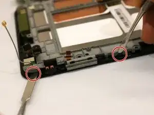
    • With the device face down, pull up on the top left side of the metal frame while pushing out the plastic tooth using two spudgers.

    • Gently lift until you feel the tension of the adhesive on the right side.

    • Once you feel tension, slide a spudger tool down the length of the right side to remove the adhesive.

    • Be sure to move the tool straight down the side. There is a thin copper film that can be crumpled if the spudger enters from the side.

  13. a26SexQfeUibHx4F
    • The motherboard is soldered to the black screen frame by an orange film tab.

    • With the screen now removed, it too can be replaced.

Conclusion

To reassemble your device, follow these instructions in reverse order. Take your e-waste to an R2 or e-Stewards certified recycler.

Madison Cranmer

Member since: 11/04/17

385 Reputation

0 comments