Introduction
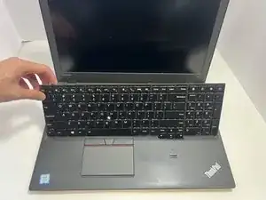
This guide explains how to replace the motherboard of a Lenovo ThinkPad P50s. The motherboard is the main circuit board that powers and connects all internal components, such as the RAM, processor, and graphics card, enabling them to communicate.
Common signs of a failing motherboard include slow performance, boot issues, frequent errors, random restarts, an unresponsive touchpad or keyboard, or the laptop not turning on. However, these symptoms can also have other causes. For more troubleshooting steps, refer to the Lenovo ThinkPad P50s troubleshooting pages here. If you’ve confirmed the motherboard has failed, follow this guide to replace it.
There are many cable connectors that need to be disconnected to complete this repair. For additional information and tips on disconnecting cables, refer to the guide on Recognizing and Disconnecting Cable Connectors.
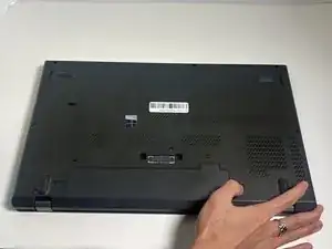
Before starting, disable the built-in battery. Instructions can be found on page 123 here. Turn off the laptop and disconnect the charging cable before proceeding.
-
-
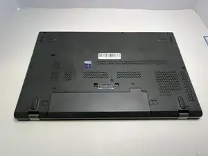
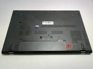
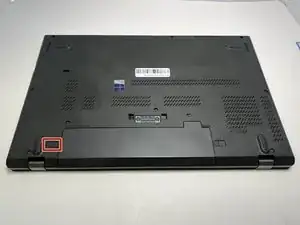
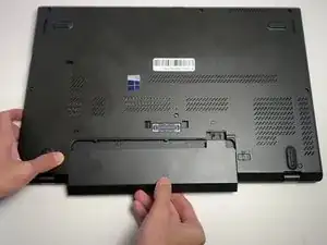
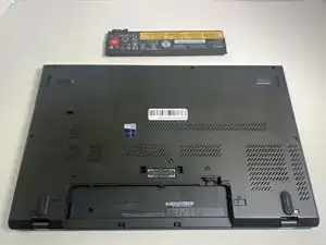
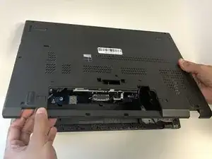
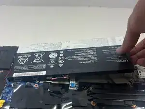
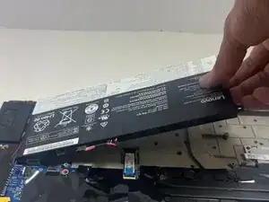
With your thumb slide the left lock switch button outward while sliding the battery out with your other hand.
-
-
-
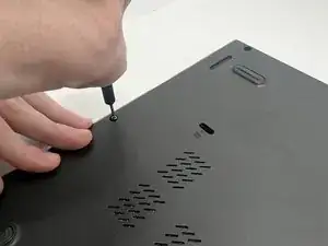
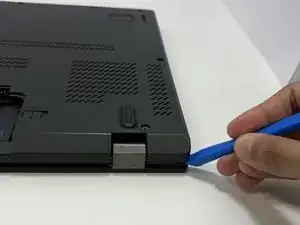
With the plastic opening tool, pry up the base cover.
-
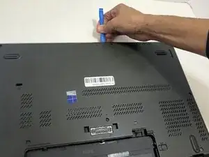
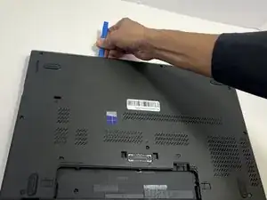
Slide the opening tool around the edge of the laptop to release the snap tabs.
-
-
-
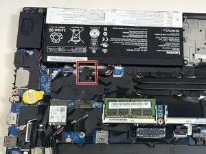
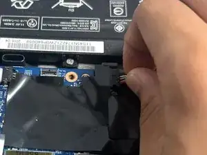
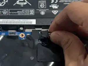
With your fingers or a spudger, disconnect the battery cable from the motherboard.
-
Use the point of a spudger to push on alternating sides of the connector to "walk" it out of its socket.
-
-
-
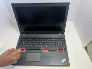
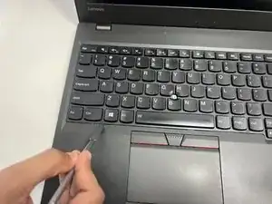
Use a spudger to push on the indents in the keyboard approximately 2.5 mm forward to reveal the 1.7 mm screws.
-
-
-
Use a Phillips #00 screwdriver to remove the six 2.5 mm screws on the keyboard
-
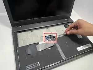
Flip the keyboard forward to lie flat on the keys, exposing the two ribbons.
-
-
-
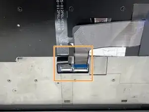
Use a spudger or a clean fingernail to flip up the locking flap—this is the unlocked position.
-
Use tweezers or your fingers to gently pull the cables out of their sockets.
-
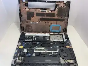
Remove the keyboard from the laptop.
-
-
-
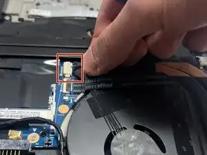
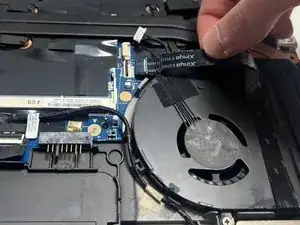
Use the point of a spudger to push on alternating sides of the fan connector to "walk" it out of its socket.
-
-
-
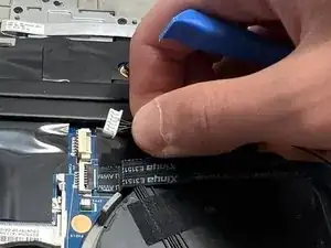
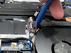
Use the opening tool to lift up the locking flap on the power button cable.
-
Use tweezers or your fingers to gently pull the cable out of its socket.
-
-
-
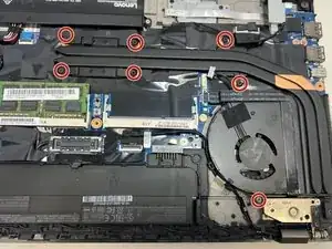
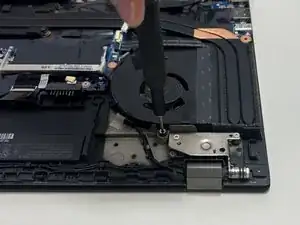
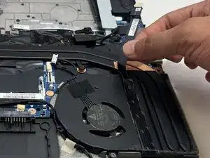
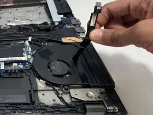
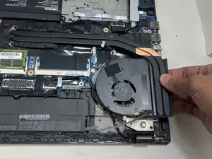
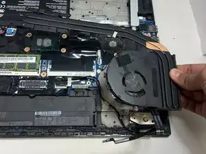
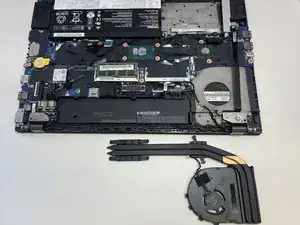
Use a Phillips #00 screwdriver to loosen the seven 2.5 mm captive screws securing the fan assembly to the motherboard.
-
-
-
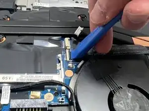
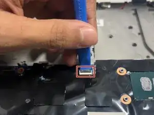
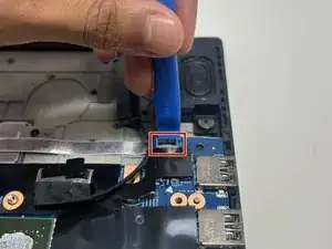
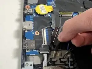
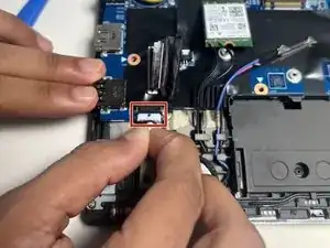
Use the plastic opening tool to lift the locking pad on the trackpad cable connector to the unlocked position.
-
Use tweezers or your fingers to gently pull the cable out of its socket.
-
-
-
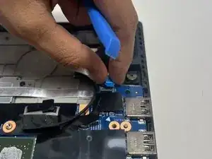
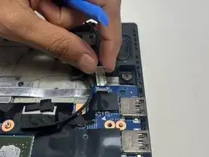
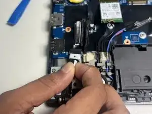
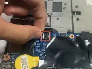
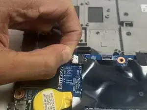
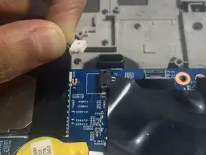
Use the plastic opening tool to lift the locking pad on the fingerprint cable.
-
Use tweezers or your fingers to gently pull the cable out of its socket.
-
-
-
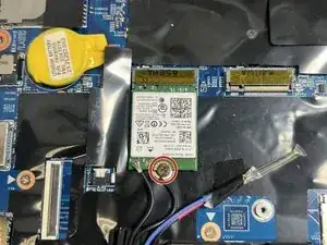
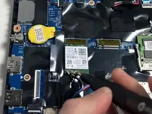
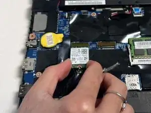
Use a Phillips #00 screwdriver to remove the single 2.5 mm screw securing the WLAN card.
-
Slide the WLAN card out of its socket.
-
-
-
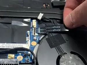
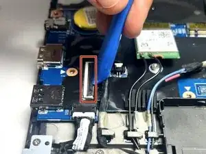
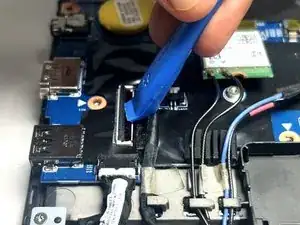
Use the opening tool to lift the locking flap on the LCD cable connector.
-
Use tweezers or your fingers to gently pull the LCD cable out of its socket.
-
-
-
Pull the DC-in cable connector out with your fingers. If you aren't able to pull it by the connector, use the point of a spudger to push on alternating sides of the connector to "walk" it out of its socket.
-
-
-
Use the point of a spudger to push on alternating sides of the speaker assembly cable connector to remove it from its socket.
-
-
-
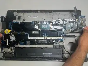
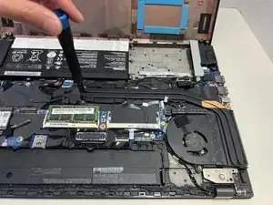
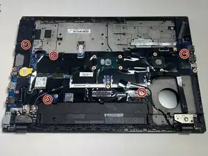
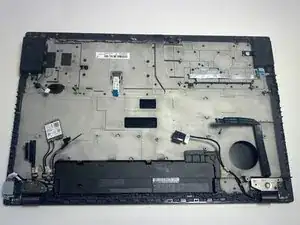
Use a Phillips #00 screwdriver to remove the five 2.5 mm screws securing the motherboard to the chassis.
-


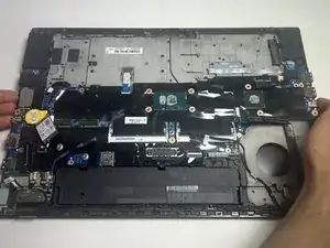

To reassemble your device, follow these instructions in reverse order. Take your e-waste to an R2 or e-Stewards certified recycler.