Introduction

Follow this guide to replace the screen hinges in your Lenovo ThinkPad T16 Gen 3 laptop.

If opening or closing your laptop lid feels extremely stiff or loose, or if it isn't staying open or closed, your hinges may need to be replaced.

The Lenovo part number for the hinges is 5H51L77350.

If you need to replace your entire screen, follow this guide instead.

  1. xxNOPMoGoWYkTGQE
    xxNOPMoGoWYkTGQE
    GUnBXysNB2NxAUKS
    YNC2EdVroQAhUjPC
    • For your safety, discharge your battery below 25% before disassembling your laptop. A charged battery may catch fire if damaged. If your battery is swollen, take appropriate precautions.

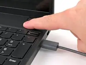
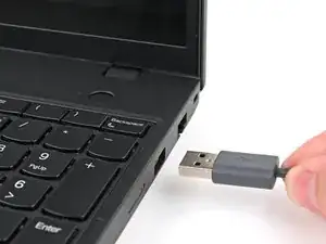
    • Completely shut down your laptop (don't just put it in sleep mode) and disconnect all cables.

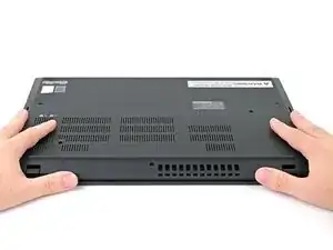
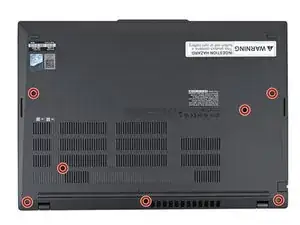
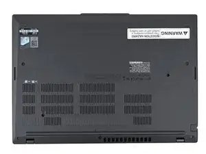
    • Flip the laptop upside-down, and rotate it so the screen hinge faces towards you.

  2. RbWgoD2uaUqYYHy2
    RbWgoD2uaUqYYHy2
    3yXt1uueHCgFQBV2
    • Use a Phillips screwdriver to fully loosen the seven captive screws securing the base cover.

  3. xyP2CA2xDRghTaRR
    xyP2CA2xDRghTaRR
    BIgZKvTMkNb2MBQK
    ahNyGAEmIWqnirIT
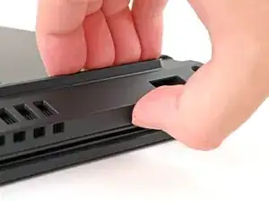
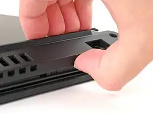
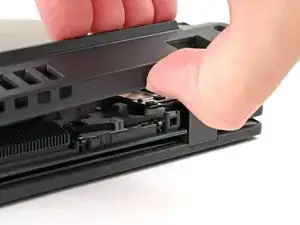
    • Insert your fingernail or an opening pick into the gap between the base cover and keyboard deck, next to one of the screen hinges.

    • Pry up the base cover until the clips unfasten.

  4. rQiUEKGPLWPWJRrm
    rQiUEKGPLWPWJRrm
    cb5tJFXBhvJPoSPQ
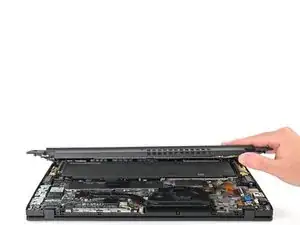
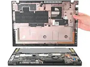
    • Grasp the base cover along the screen hinge edge and lift slowly to unfasten the remaining clips.

    • Lift and remove the base cover.

    • During reassembly, lay the base cover into the frame, inserting it into the tabs along the battery edge. Press down firmly around the perimeter to reengage all the clips.

  5. tkYPg2EhajlcGZG6
    tkYPg2EhajlcGZG6
    kewyINYhKrkeCqNM
    • Because of the battery connector's design, the only way to disconnect the battery is by physically removing it.

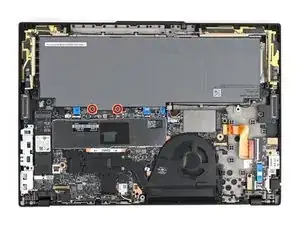
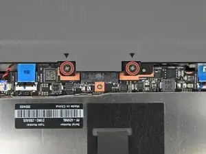
    • Use a Phillips screwdriver to fully loosen the two captive screws securing the battery connector.

  6. VbFsBodaaINR1abt
    VbFsBodaaINR1abt
    OBXrUehAO2CM5QdQ
    YXbYLqdNKDUOLNDm
    • Lift the edge of the battery with the connector to disconnect it.
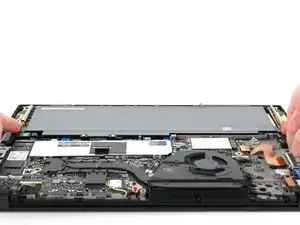
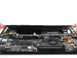
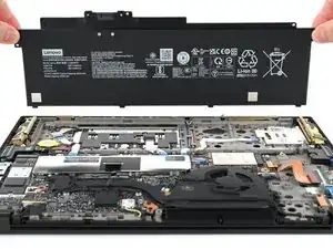
    • You may feel a little resistance from the battery connector as it disconnects—that's normal.

    • Remove the battery

    • During reassembly:

    • Slide the plastic tabs on the long edge of the battery into their recesses in the frame.

    • Lower the battery into place so the connector goes over its socket.

  7. PKYXFBPAAuGcYrGP
    PKYXFBPAAuGcYrGP
    os6UnM2gpKBvJWIx
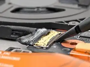
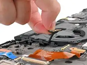
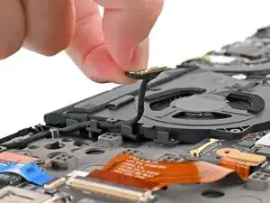
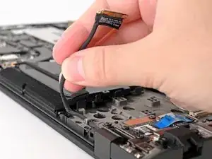
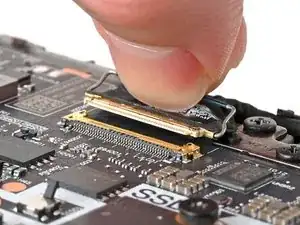
    • Use the flat end of a spudger or clean fingernail to gently push under the metal buckle of the camera cable connector to unclip it

  8. OEpdHx5bDlgXabZv
    OEpdHx5bDlgXabZv
    DaM2RVSJsQhGDTBI
    • Grab the buckle and cable together and gently pull the connector straight out of its socket.

  9. VcH6i3QfPVEFmj6k
    VcH6i3QfPVEFmj6k
    SGTjHn6hDNQnwxII
    uDiwsPbAwTltneca
    • Hold the buckle and cable together and free it from the clips holding it to the fan.

  10. uBVdoBLFH5kK3sWF
    uBVdoBLFH5kK3sWF
    dbp5t1kAMZkPZGtq
    v2txaXAXKBFGOpT1
    • Continue freeing the cable until it is only attached to the laptop at the hinge.

  11. aiAdnJ2dVF5erTi4
    aiAdnJ2dVF5erTi4
    ScWHSvsUhbiqAJUT
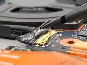
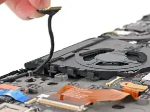
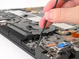
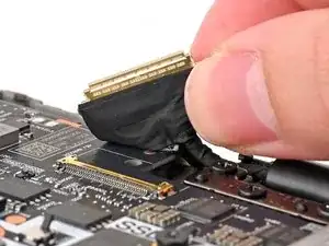
    • Use a clean fingernail or the flat end of a spudger to gently push under and lift the metal buckle of the display cable connector to unclip it

  12. sXDKP1BPScSWXuFB
    sXDKP1BPScSWXuFB
    iouXOFgxKakUTRy5
    • Grab the buckle with your fingers and gently pull the connector straight out of its socket.

  13. Jqi1sGU6YvSJjWDl
    Jqi1sGU6YvSJjWDl
    2BAOy2yBl2gtPoDj
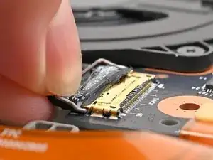
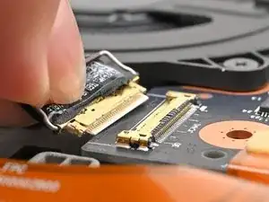
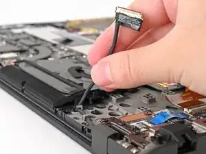
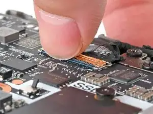
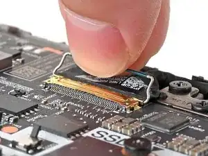
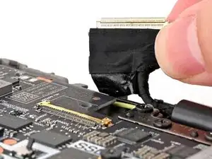
    • Hold the buckle and cable together and pull it up to separate the adhesive securing the cable to the motherboard.

  14. 5GuHg4lgfCOgCIkL
    5GuHg4lgfCOgCIkL
    oymFIPRrchFnrCDB
    T3NNXYF5T4YDC5NI
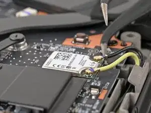
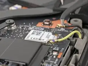
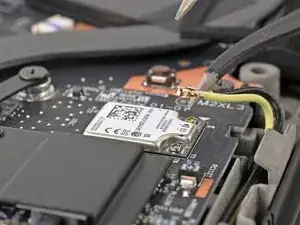
    • Insert an arm of your angled tweezers under the metal neck of one of the coaxial connectors on the Wi-Fi card and lift straight up to disconnect it.

    • Repeat for the other connector.

    • During reassembly, use tweezers to hold the connector in place over its socket and gently press down with your finger or a spudger—the connector should "snap" into place. If you're having trouble, reposition the head and try again.

  15. GLaQiFCpmQ4LiLDi
    GLaQiFCpmQ4LiLDi
    nY4PsWFSYSJSSfWI
    EZdOhOWMaRGUjKPG
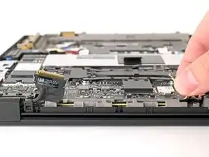
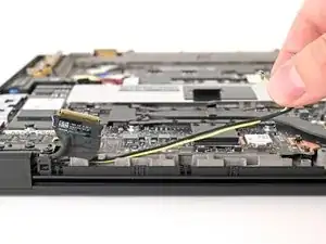
    • Grab both Wi-Fi antenna cables and guide them out of their clips on the frame until they're only attached to your laptop at the hinge.

  16. IM2YsF5VOTgkUyjc
    • Open your laptop 180 degrees (so it's completely flat) and lay it keyboard side down on your work surface.

    • Optionally, you can place a soft, clean cloth under your laptop to protect the screen and keyboard.

  17. VYiWSHNZHxIvWR43
    VYiWSHNZHxIvWR43
    sgBDxtCVGlMpSH2p
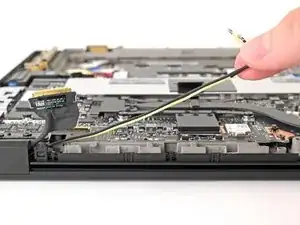
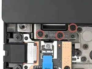
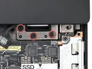
    • Use a Phillips screwdriver to remove the six 6.5 mm‑long screws securing the hinges to the laptop.

  18. UeJmehginr1njLcJ
    UeJmehginr1njLcJ
    NFUYXa2SovPZ2qVM
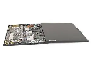
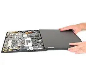
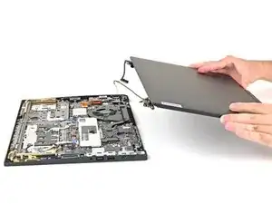
    • Lift the screen assembly straight up and remove it from the laptop.

    • Reassembly steps:

    • Make sure the screen hinges are open 180 degrees and guide them into their recesses in the frame.

    • Install and partially tighten the four hinge screws.

    • Close your laptop and make sure the screen is properly aligned. If it clicks or snaps, readjust the alignment.

    • Fully tighten the hinge screws.

  19. go3KMfnuBMmogdmW
    • Set the screen assembly down so the display is facing up.

  20. OpL52sbww1loeBs2
    OpL52sbww1loeBs2
    yo3EGlB5IyFqc2Da
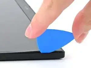
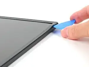
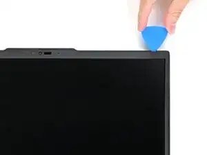
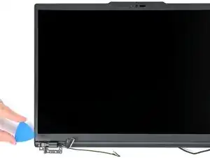
    • Insert the tip of an opening pick at a downward angle between the bezel and screen assembly, near the top right corner.

    • Lower the pick so it's flat with the screen and the tip is under the screen bezel.

  21. QoAp21dypU1DBMQw
    QoAp21dypU1DBMQw
    JnYPcUkOIQkp3Ua2
    YQtYyIGKQXMWurUt
    • Don’t insert your pick further than the tip, as you might damage the display

    • Slide your opening pick down the right edge to unfasten the bezel clips.

  22. jKITLFwyFqXgS6wA
    jKITLFwyFqXgS6wA
    rsO3XlTnRlE2Lqwq
    2XsVfPZYWBH3IoZL
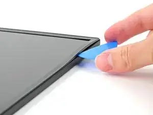
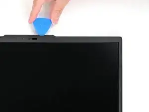
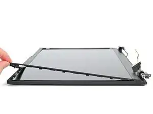
    • Re-insert your opening pick near the top right corner.

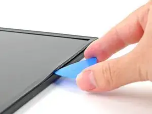
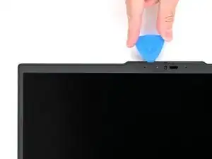
    • Slide your opening pick around the top right corner to unfasten the frame clips, stopping before you hit the webcam.

    • Remove the opening pick.

  23. ISEFPlbOvIcWLEwM
    ISEFPlbOvIcWLEwM
    eMRkTIfZetjhHlcB
    BsCdYwNbbedSlSwH
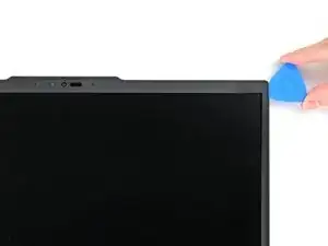
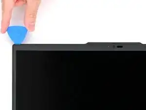
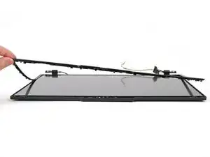
    • Re-insert your pick to the left of the webcam and slide it towards the top left corner and down the left edge to unfasten the remaining clips.

  24. 62etxPSBEKZdxaJ6
    62etxPSBEKZdxaJ6
    HDu6eVuNRTaERQS2
    o2AwpyfZ3noLe3CP
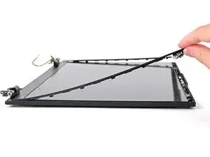
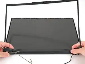
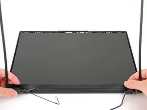
    • Gently lift the bezel on the right, top, and left edge to ensure all the clips are fully unfastened.

  25. WXylJWYhSKASoNTQ
    WXylJWYhSKASoNTQ
    QPgT1tE5uANGEZy1
    • The bottom edge of the bezel is held in place with strong adhesive and clips.

    • Ensure you're separating the bottom edge of the bezel from the protective film and not the protective film from the screen. If the film starts to peel up, gently press it back into place before you continue peeling up the bezel.

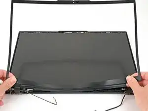
    • Use your fingers to slowly peel the bottom edge of the bezel from the protective film on the display.

    • If you're having a hard time separating the adhesive, use your opening pick to slice through the adhesive, being very careful not to cut the film. If it is still difficult, use an iOpener or hair dryer to lightly heat the bottom edge of the bezel.

  26. TNTy46ANtClD1pGy
    TNTy46ANtClD1pGy
    QgUxkCfnRWN1ot2d
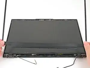
    • Once the adhesive is completely separated, lift the bottom edge of the bezel straight up to unfasten its clips.

    • Remove the bezel.

    • To re-install this bezel or install a new one, you may need to replace the adhesive if the bezel isn't sticking correctly. If your replacement part does not include adhesive, use thin, double-sided tape. Use the 5mm strips for the bottom and the 1mm strips around the top and sides. Remove all residue from the original adhesive before replacing.

  27. yQN5BqQwkhQkGXbT
    yQN5BqQwkhQkGXbT
    rNBELu5YKeCKeWUC
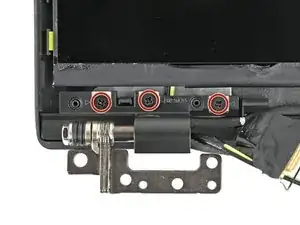
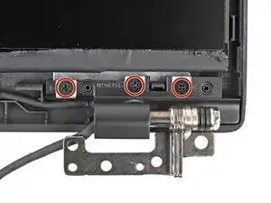
    • Use a Phillips screwdriver to remove the six 3.75 mm‑long screws securing the hinges (3 in each).

  28. PXKq1Os6UYC4LAYI
    PXKq1Os6UYC4LAYI
    3w5EQQIiEhsj41JH
    1WjYiT6pEGQCZbPD
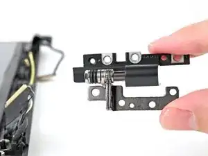
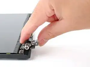
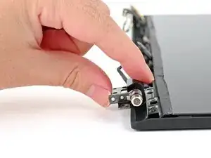
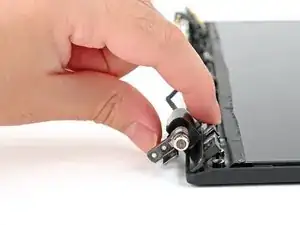
    • Use your fingers to rotate one of the hinges downwards to unfasten the clips holding it in place.

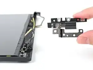
    • Remove the hinge from its recess

  29. AHSILL3MPhmhpqiJ
    AHSILL3MPhmhpqiJ
    FTIKp5xidUjKh2xX
    HAu3HKAofYLYJPhb
    • Repeat the process to remove the other hinge.

Conclusion

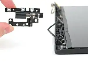
Compare your new replacement part to the original part—you may need to transfer remaining components from the new part before you install it.

To reassemble your device, follow these instructions in reverse order.

Repair didn’t go as planned? Try some basic troubleshooting, or ask our Answers community for help.

Nick Schultz

Member since: 24/03/24

19090 Reputation

0 comments